Liquid crystal module and liquid crystal display screen

A liquid crystal module and backplane technology, which is applied in nonlinear optics, instruments, optics, etc., can solve the problems that the direct type cannot be thinned and the cost of the side-mounted liquid crystal module is high, so as to improve the uniformity of illumination and achieve thin The effect of optimizing the design and preserving the reliability

Inactive Publication Date: 2016-10-12
GUANGZHOU SKYWORTH PLANE DISPLAY TECH
View PDF11 Cites 13 Cited by
  • Summary
  • Abstract
  • Description
  • Claims
  • Application Information

AI Technical Summary

Problems solved by technology

[0005] The technical problem to be solved by the present invention is to provide a liquid crystal module and a liquid crystal display in view of the deficiencies of the prior art, so as to solve the problems of the high cost of the side-entry liquid crystal module and the inability to realize thinning of the direct-type liquid crystal display in the prior art. question

Method used


Image

  • Liquid crystal module and liquid crystal display screen
  • Liquid crystal module and liquid crystal display screen
  • Liquid crystal module and liquid crystal display screen

Examples


Embodiment 1

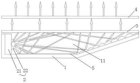
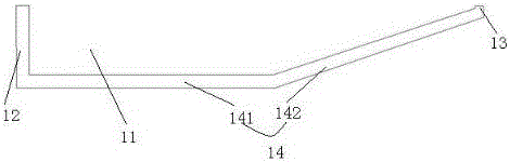
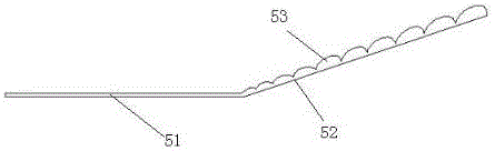
[0030] This embodiment provides a liquid crystal module, such as figure 1 and 2 As shown, it includes a backplane 1, a backlight 2, a diffusion plate 3 capable of diffusing the light emitted by the backlight 2, an optical film (not shown in the figure), glass 4 and a reflector; the backplane 1 includes The wedge-shaped bottom plate 14 and the first side plate 12 and the second side plate 13 arranged at both ends of the bottom plate 14 form a wedge-shaped cavity 11 with an opening. The backlight 2 is disposed on the inner surface of the first side plate 12 , and the glass 4 and the diffusion plate 3 are sequentially stacked at the opening of the cavity 11 of the back plate 1 to close the opening. The optical film is located between the glass 4 and the diffusion plate 3, and is attached to the upper surface of the diffusion plate 3, so that the light emitted by the backlight 2 will pass through the diffusion plate 3 and the optical film in sequence, and finally pass through the...

Embodiment 2

[0037] This embodiment provides a liquid crystal module, the structure of which is basically the same as that of Embodiment 1, the difference is that, as Figure 4 and Figure 5 As shown, the backlight 2 includes a PCB board 21, a light source 22 installed on the PCB board 21 and electrically connected to the PCB board 21, and a light source 22 sleeved on the light source 22 for generating Optical coupler 23 for light mixing. The optical coupler 23 can be made of glass, PMMA, PC or MS and other materials with good optical properties and chemical stability, which specifically includes a first side 231, a second side 232 and a top side 233 Construct a body with an opening facing the light source 22, the body of the optical coupler 23 is connected to the PCB board 21, the PCB board 21 covers the opening of the body and forms a closed space 234 with the body, the light source 22 is placed Inside the enclosed space 234 . The body is in an inverted trapezoid shape, that is, the f...


PUM


Abstract

The invention discloses a liquid crystal module and a liquid crystal display screen. The liquid crystal module comprises a back plate, a backlight source, a diffusion plate and a glass, wherein the backlight source is arranged on a side edge of the back plate; the diffusion plate is arranged on the back plate; the glass is arranged above the diffusion plate; the back plate is provided with a cavity used for mixing light; a bottom wall of the cavity, opposite to the diffusion plate, has a wedge-shaped structure; a wedge-shaped reflector is arranged on the bottom wall of the cavity. The liquid crystal module adopts air as a light guide plate, utilizes the cavity thereof to fully mix light and does not use the light guide plate to mix light, so that the problems of the liquid crystal module in the prior art that the cost is high and the light guide plate can expand in the working process and influence the light emission of the backlight source are solved. The thickness of the light-near side of the liquid crystal module is basically consistent to that of the traditional straight lower module; the reliability of the straight lower module is remained; the distance-light side reflects through the special structure of a white reverse surface, so that the thickness is consistent to that of the traditional lateral light module and the thinning design of the lateral light module is realized.

Description

technical field [0001] The invention relates to the technical field of liquid crystal display, in particular to a liquid crystal module and a liquid crystal display. Background technique [0002] A liquid crystal display (LCD, Liquid Crystal Display) has many advantages such as a thin body, power saving, and no radiation, and has been widely used. Most of the liquid crystal display devices currently on the market are backlight liquid crystal display devices, which include a liquid crystal panel and a liquid crystal module (backlight module). The working principle of the liquid crystal panel is to place liquid crystal molecules between two parallel glass substrates. There are many small vertical and horizontal wires between the two glass substrates. The direction of the liquid crystal molecules is controlled by electrifying or not, and the light of the liquid crystal module is refracted. Come out to generate the picture. Since the liquid crystal panel itself does not emit l...

Claims


Application Information

Patent Timeline
Patent Type & Authority Applications(China)
IPC IPC(8): G02F1/13357
CPCG02F1/133615
Inventor 王博朱杉婷林敏宏王玉年沈思宽吴哲陈天航文勇兵
Owner GUANGZHOU SKYWORTH PLANE DISPLAY TECH
Why Eureka
Try Eureka