Rear projection screen and projection system
A screen and projection lens technology, applied in optics, instruments, projection devices, etc., can solve problems such as reducing user experience and inconsistency in image color, and achieve the effect of improving user experience, improving consistency, and reducing color shift.
- Summary
- Abstract
- Description
- Claims
- Application Information
AI Technical Summary
Problems solved by technology
Method used
Image

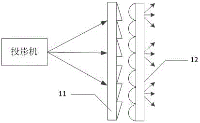
Examples
Embodiment 1
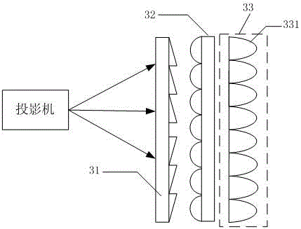
[0041] like Figure 3A As mentioned above, the rear projection screen provided by Embodiment 1 of the present invention includes: a Fresnel lens layer 31 , a lenticular lens layer 32 and a microlens layer 33 arranged in sequence along the light emitting direction of the projection lens. Wherein, the microlens layer 33 includes: a plurality of microlens groups distributed in an array, and the microlens groups at least include a first microlens 331 . Specifically, the first microlens 331 is a positive lens, and the focal length of the first microlens 331 is greater than the focal length of the lenticular lens of the lenticular lens layer 32 .
[0042] Preferably, the first microlens and the lenticular lens are juxtaposed and have comparable sizes.
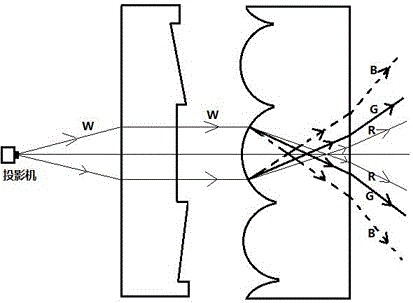
[0043] The light emitted from the projection lens enters the Fresnel lens layer 31 and the lenticular lens layer 32 of the rear projection screen in sequence, and finally passes through the microlens layer 33 and enters human eyes t...
Embodiment 2
[0055] like Figure 4A As mentioned above, another rear projection screen provided by Embodiment 2 of the present invention includes: a Fresnel lens layer 41 , a lenticular lens layer 42 and a microlens layer 43 arranged in sequence along the light emitting direction of the projection lens. Among them, the difference from Embodiment 1 is that, in addition to the first microlens 431, the microlens group of the microlens layer 43 also includes The second microlens 432 is provided, wherein the second microlens 432 is a negative lens, and the dispersion coefficient of the first microlens 431 is greater than that of the second microlens 432 .
[0056] Specifically, the dispersion coefficient of the first microlens 431 is greater than that of the second microlens 432. As mentioned above, the dispersion coefficient is related to the material of the lens and affects the refractive index of the light beam. In the embodiment of the present invention, the second A refractive index of a ...
Embodiment 3
[0078] Based on the same inventive concept, an embodiment of the present invention provides a projection system, which includes any one of the above rear projection screens. The projection system may be a rear projection splicing display system, and the projector of the projection system may be a laser projector. In practical applications, images can be displayed after matching the focal length of the projector and the focal length of the rear projection screen.
[0079] Specifically, it can be as Figure 7 As shown, the projection system adopts the projection screen technical solution as shown in the second embodiment.
[0080] Due to the use of the projection screen in the first or second embodiment above, when the projection system in the embodiment of the present invention displays images, it can effectively reduce the difference in spatial energy distribution of white light after passing through the rear projection screen, and the color shift of white light is low under d...
PUM
 Abstract
Description
Claims
Application Information
 - R&D
- Intellectual Property
- Life Sciences
- Materials
- Tech Scout
- Unparalleled Data Quality
- Higher Quality Content
- 60% Fewer Hallucinations
Browse by: Latest US Patents, China's latest patents, Technical Efficacy Thesaurus, Application Domain, Technology Topic, Popular Technical Reports.
© 2025 PatSnap. All rights reserved.Legal|Privacy policy|Modern Slavery Act Transparency Statement|Sitemap|About US| Contact US: help@patsnap.com