New energy vehicle power battery cooling system

A technology for power batteries and new energy vehicles, which is applied in the field of power battery cooling systems for new energy vehicles, can solve problems such as explosions and shorten the life of power batteries, achieve uniform distribution, and improve the cooling effect.

Inactive Publication Date: 2016-10-12
JINAN LUFANG ZHIHE INFORMATION TECH CO LTD
View PDF10 Cites 4 Cited by
  • Summary
  • Abstract
  • Description
  • Claims
  • Application Information

AI Technical Summary

Problems solved by technology

[0006] In order to solve the deficiencies in the prior art, the present invention provides a new energy vehicle power battery heat dissipation system, which is used for temperature control of the power battery, especially for cooling the main surface, so as to solve the problem of life reduction and explosion caused by the heating of the power battery. And other issues

Method used


Image

  • New energy vehicle power battery cooling system
  • New energy vehicle power battery cooling system
  • New energy vehicle power battery cooling system

Examples


Embodiment 1

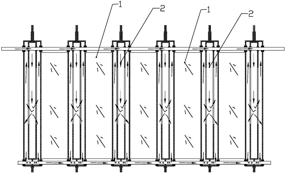
[0050] Embodiment 1, in the process of manufacturing the temperature equalizing component 2, it is necessary to consider the deformation and expansion caused by the heating process of the battery core 1, and comprehensively utilize the deformation to achieve the purpose of effectively controlling the temperature rising process.

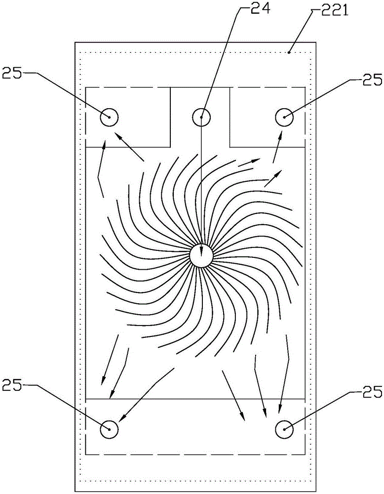
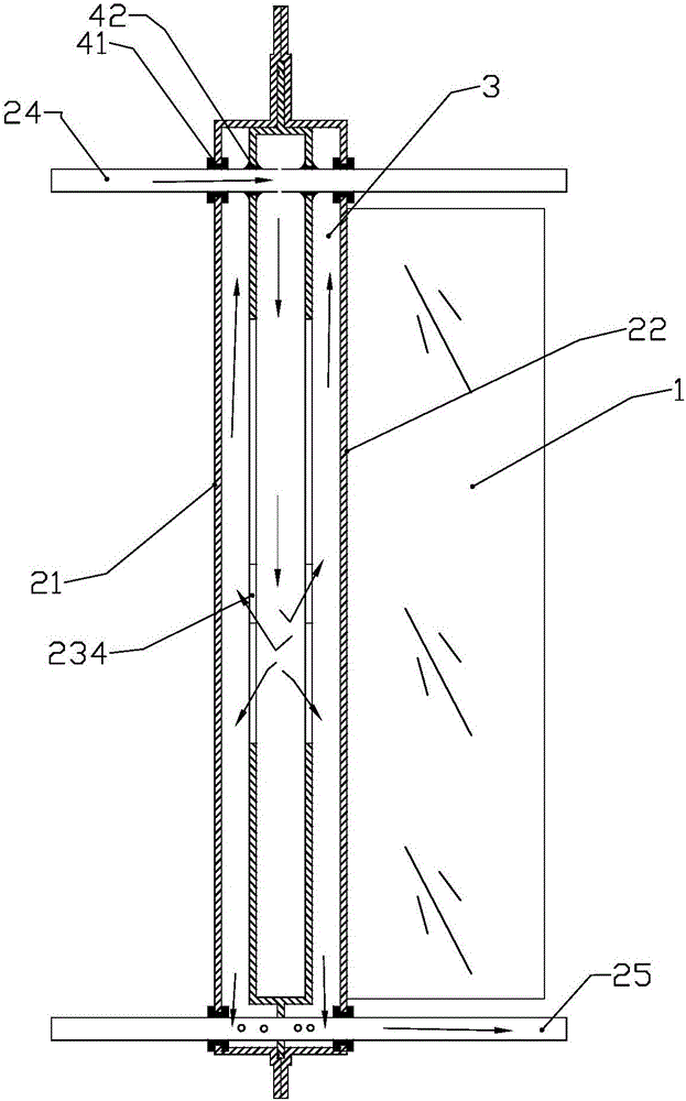
[0051] The temperature uniform assembly 2 includes a left housing 21, a right housing 22, a liquid guide piece 23, a liquid inlet pipe 24, and a liquid outlet pipe 25, wherein the left and right housings are symmetrical structures, and are integrally formed by buckling and surrounding welding , to form a complete shell, and take the left shell 21 as an example to describe in detail, the left shell 21 is stamped from a thin plate made of stainless steel, and is designed as an outwardly convex structure 211, which is used to cooperate with the liquid guide sheet. refer to Figure 5 , and a groove 212 for clamping the battery core is provided on the oute...

Embodiment 2

[0067] Embodiment two, such as Figure 11 , the inner surfaces of the left and right housings are provided with spiral protrusions 21' that are spirally distributed from the middle to the surroundings. The spiral protrusions 21' are arranged opposite to the above-mentioned spiral cloth liquid groove 235, and are basically arranged in the opposite direction of the spiral distribution groove , form a uniform structure, and under the action of external force, disperse to the outside, and improve the cooling and flow rate near the surface of the outer shell.

[0068] The above-mentioned cooling liquid adopts low-viscosity mixed oil, which has anti-explosion effect. Its components include: 150N three-type base oil with a mass ratio of 95-99%, 1.0-5.0% diphenolic propane, 0.005% methyl silicone oil or methyl Based silicone oil ester, 0.05% tricresyl phosphate, 0.1% sulfurized polyisobutylene, 100PPM demulsifier T1001 or LZ5957, and 0.2-0.3% succinate sulfonate, this special mixed oi...


PUM

PropertyMeasurementUnit
porosityaaaaaaaaaa

Abstract

The invention discloses a new energy vehicle power battery cooling system used for solving the temperature raising problem of an existing battery pack. The system comprises battery cores and uniform-temperature assemblies, wherein the battery cores and the uniform-temperature assemblies are stacked at intervals. Each uniform-temperature assembly comprises a left shell, a right shell, a liquid guide piece, a liquid inlet pipe and a liquid outlet pipe, wherein the left shell and the right shell are of a symmetric structure, an inner cavity of the liquid guide piece is a cooling liquid channel, the edge of the liquid guide piece is embedded in a connection seam of the left shell and the right shell, glue seams are formed in the periphery of the liquid guide piece, uniform-temperature fields are formed between one side of the liquid guide piece and the left shell and between the other side of the liquid guide piece and the right shell respectively, the two side faces of the liquid guide piece are provided with center holes and spiral liquid distribution slots, the liquid inlet pipe and the liquid outlet pipe are externally connected with a liquid pump and a cooler to form a circulating pipeline, and a cooling medium flowing channel is formed. Flowing speed of cooling media in the uniform-temperature assemblies can be controlled, and the aim of controlling temperature in the battery cores is achieved.

Description

technical field [0001] The invention relates to the technical field of new energy power batteries, specifically a heat dissipation system for new energy vehicle power batteries with better temperature control effect. Background technique [0002] The power battery is the core component of the electric vehicle, and its performance directly affects the performance of the electric vehicle. The power battery is generally large in size and occupies the position of the chassis of the vehicle, and its heat dissipation effect is very poor. [0003] Today's batteries are generally cooled by natural cooling, air cooling or water cooling. Since power batteries are generally lithium batteries, taking lithium batteries as an example, the best internal charge and discharge temperature should not be higher than 140°C, and the external temperature should not be high. Temperature below 80°C, otherwise the service life and charge and discharge effect of the battery will be reduced. [0004] ...

Claims


Application Information

Patent Timeline
Patent Type & Authority Applications(China)
IPC IPC(8): H01M10/613H01M10/617H01M10/625H01M10/6567H01M10/6568H01M10/653H01M2/08H01M50/183
CPCH01M10/613H01M10/617H01M10/625H01M10/653H01M10/6567H01M10/6568H01M50/183Y02E60/10
Inventor 陈华锋
Owner JINAN LUFANG ZHIHE INFORMATION TECH CO LTD
Why Eureka
Try Eureka