Terminal short circuit protection method and device
A terminal short-circuit and terminal technology, which is applied in circuit devices, battery circuit devices, safety/protection circuits, etc., to achieve the effect of improving accuracy, ensuring safe use, and reducing the probability of short-circuit misjudgment
- Summary
- Abstract
- Description
- Claims
- Application Information
AI Technical Summary
Problems solved by technology
Method used
Image
Examples
Embodiment 1
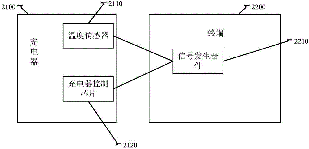
[0097] Embodiment 1. In this embodiment, a temperature sensor is installed in the charger in the terminal system, and the temperature sensor is connected to the signal generator, and the charger control chip corresponding to the charger is also connected to the signal generator.
[0098] figure 2 It is a schematic diagram of a terminal system for terminal short-circuit protection according to an exemplary embodiment 1, as shown in figure 2 As shown, the terminal system includes: a charger 2100 and a terminal 2200 , wherein the charger 2100 is equipped with a temperature sensor 2110 and a charger control chip 2120 . And the terminal 2200 has a signal generating device 2210 on it. Both the temperature sensor 2110 and the charger control chip 2120 are connected to the signal generating device 2210 .
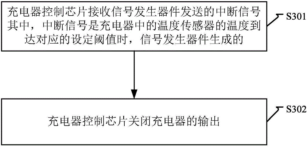
[0099] image 3 It is a flow chart of a terminal short-circuit protection method shown according to an exemplary embodiment 1, such as image 3 As shown, the following steps S...
Embodiment 2
[0103] Embodiment 2. In this embodiment, temperature sensors are respectively installed in the battery, the charger, and the motherboard circuit in the terminal system, and each temperature sensor is connected to the signal generating device, and the battery protection chip corresponding to the battery corresponds to the charger. The charger control chip and the power management chip corresponding to the main board circuit components are also connected to the signal generator respectively.
[0104] Figure 4 It is a schematic diagram of a terminal system for terminal short-circuit protection according to an exemplary embodiment 2, as shown in Figure 4 As shown, the terminal system includes: a charger 4100 and a terminal 4200 , wherein the charger 4100 is equipped with a temperature sensor 4110 and a charger control chip 4120 . And the terminal 4200 has a signal generating device 4210 , a battery 4220 , and a main board circuit element 4230 . The battery 4220 has a temperatu...
Embodiment 3
[0148] Embodiment three, Figure 7 It is a block diagram of a terminal short-circuit protection device according to an exemplary embodiment 3. The device is applied to a power management chip of a terminal system. In the terminal system, there is a temperature sensor on the main board circuit element, and the temperature sensor and the power management chip are respectively connected to the signal generation device connection. Such as Figure 7 As shown, the device includes: a receiving module 610 and a cutting module 620 . Wherein, the cutting module 620 further includes a first cutting sub-module 621 .
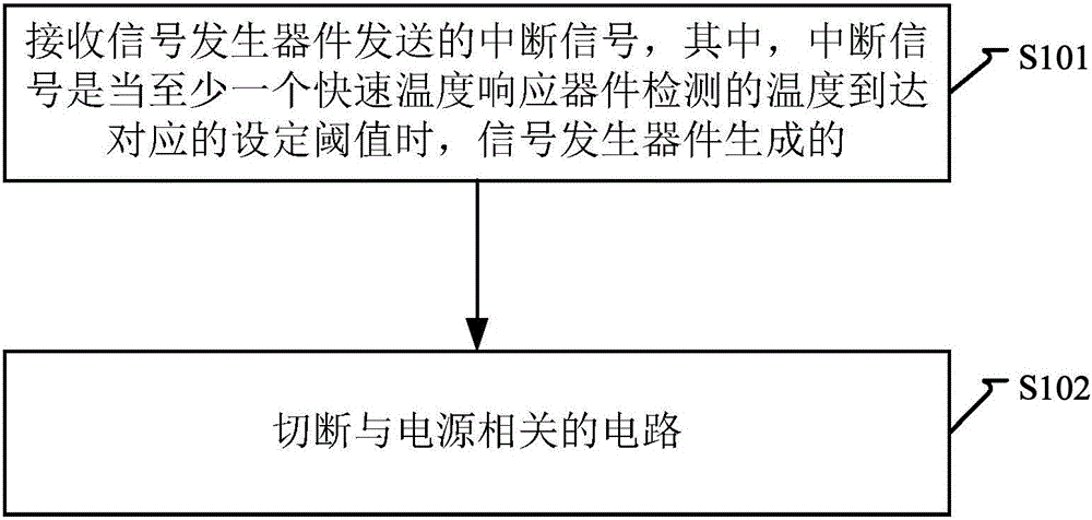
[0149] In this embodiment, the receiving module 610 receives the interrupt signal sent by the signal generating device, wherein the interrupt signal is generated by the signal generating device when the temperature detected by the temperature sensor reaches a corresponding set threshold.
[0150] The first disconnection sub-module 621 in the disconnection module 620 contr...
PUM
 Abstract
Description
Claims
Application Information
 - R&D
- Intellectual Property
- Life Sciences
- Materials
- Tech Scout
- Unparalleled Data Quality
- Higher Quality Content
- 60% Fewer Hallucinations
Browse by: Latest US Patents, China's latest patents, Technical Efficacy Thesaurus, Application Domain, Technology Topic, Popular Technical Reports.
© 2025 PatSnap. All rights reserved.Legal|Privacy policy|Modern Slavery Act Transparency Statement|Sitemap|About US| Contact US: help@patsnap.com


