Low-voltage transformer area physical topology online generating and real-time monitoring method and system

A technology of real-time monitoring system and physical topology, applied in the direction of information technology support system, electrical components, sustainable buildings, etc., can solve the problems of aggravated line confusion in the station area, heavy workload of on-site personnel, manual sorting, etc., and achieve economical Benefits and social benefits, good economic benefits and social benefits, and the effect of improving work efficiency

Active Publication Date: 2016-10-12
SHANDONG SENTER ELECTRONICS
View PDF2 Cites 37 Cited by
  • Summary
  • Abstract
  • Description
  • Claims
  • Application Information

AI Technical Summary

Problems solved by technology

[0003] 1. The basic information of the station area is incomplete; for some old station areas, due to the long period of time, the original saved data was lost, or the basic information was not updated in time after the later line reconstruction, resulting in a mismatch between the data and the actual line
[0004] 2. Users privately connect power lines, especially at the junction of the station area, which is more likely to cause crossover, which aggravates the confusion of the line in the station area
[0008] The simple use of power carrier communication has two obvious disadvantages: in the case of adjacent substations sharing high voltage, common ground, and common cable trench, it is easy to cause misjudgment due to the cross-connection of carrier signals; the power carrier signal is a high-frequency signal, attenuation S

Method used


Image

  • Low-voltage transformer area physical topology online generating and real-time monitoring method and system
  • Low-voltage transformer area physical topology online generating and real-time monitoring method and system
  • Low-voltage transformer area physical topology online generating and real-time monitoring method and system

Examples


Embodiment 1

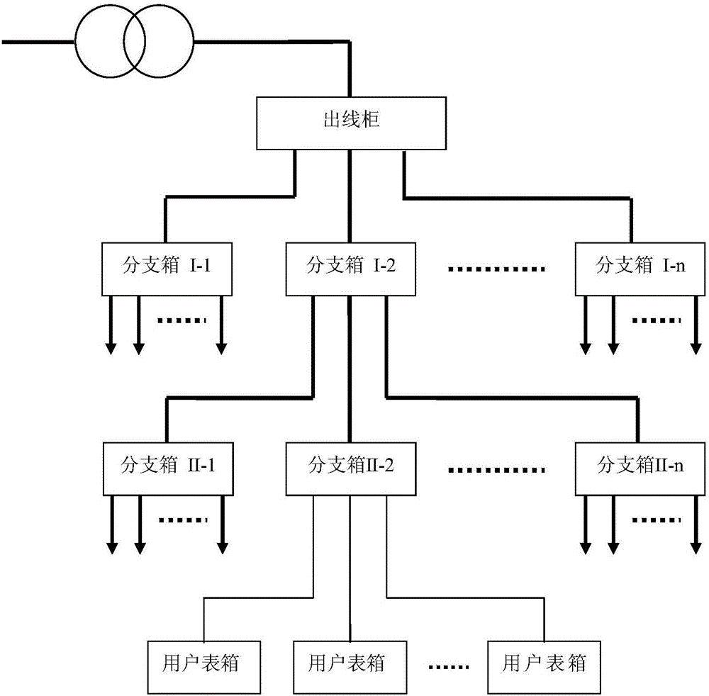
[0039] like Figure 1-2As shown, taking the tree connection as an example, the core equipment for line connection in the low-voltage station area mainly includes: distribution transformers, outlet cabinets, branch boxes, and user meter boxes. The branch box is the intermediate equipment of the line in the station area, and the outlet cabinet is the head-end equipment of the line in the station area. figure 1 The middle black thick solid line represents the busbar (A, B, C, N three-phase four-wire), and the black thin solid line represents the single-phase line distributed to the user meter box (L, N two-wire line of any phase of A, B, C ), the online generation and real-time monitoring method of the physical topology of the low-voltage platform area of ​​the present invention, comprising:

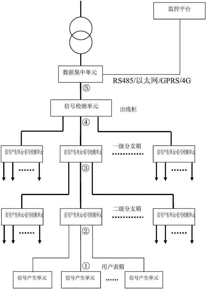
[0040] Set signal generation units at the end equipment and intermediate equipment of the line in the station area, set up signal detection units at the intermediate equipment and head-end...

Embodiment 2

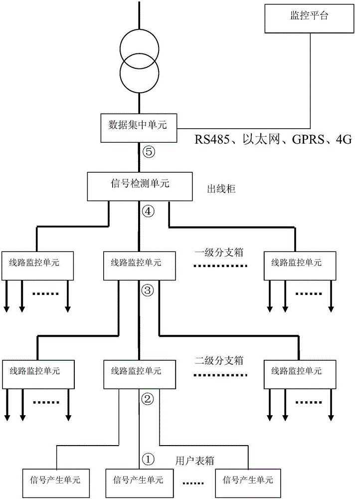
[0054] Such as image 3 As shown, on the basis of Embodiment 1, this embodiment integrates the signal generation unit and the signal detection unit provided by each intermediate device of the line in the station area, collectively referred to as the line monitoring unit, and the online generation and real-time monitoring method of its physical topology Same as Example 1.

Embodiment 3

[0056] Take the tree connection as an example, such as figure 1 As shown, the core equipment connected to the line in the low-voltage station area mainly includes: distribution transformers, outlet cabinets, branch boxes and user meter boxes. Among them, the user meter box is the terminal equipment of the station area line, and the cascaded branch box is the center equipment, the outlet cabinet is the head-end equipment of the line in the station area, such as figure 2 As shown, this embodiment provides an online generation and real-time monitoring system for the physical topology of a low-voltage station area, including a signal generation unit, a signal detection unit, and a data concentration unit, and the signal generation unit is located at the line end equipment and intermediate equipment in the station area , the signal detection unit is set at the line intermediate equipment and head-end equipment in the station area, the data concentration unit is set at the low-volt...


PUM


Abstract

The invention relates to the technical field of low-voltage distribution network line detection, in particular to a low-voltage transformer area physical topology online generating and real-time monitoring method. The method includes the steps that signal generating units, signal detecting units and a data transmitting unit are reasonably deployed on a transformer area line, and the data transmitting unit communicates with an electricity power monitoring platform; after a topology online generating instruction is sent, all branch line physical topologies are generated one by one and are combined into an integral low-voltage transformer area physical topology to be stored; the generated physical topology is compared with that stored before, and if the generated physical topology is different from that stored before, the change position is marked. The invention further provides a low-voltage transformer area physical topology online generating and real-time monitoring system. The signal generating units are arranged on equipment at the tail end and the middle of the transformer area line, the signal detecting units are arranged on equipment in the middle and the head end of the transformer area line, and the data transmitting unit is arranged at the low-voltage side of a distribution transformer. The transformer area line physical topology can be generated on line and monitored in real time, topology changes of the line are found in time, and reliable operation of an electric system is ensured.

Description

technical field [0001] The invention relates to the technical field of detection of low-voltage distribution network lines, in particular to a method and system for on-line generation and real-time monitoring of the physical topology of a low-voltage station area. Background technique [0002] In recent years, with the rapid development of the power grid, the hardware facilities in the distribution transformer area have been greatly improved. The marketization of the power system has put forward more refined management requirements for the power management department. The need to reduce consumption and loss is more urgent. It has become an important indicator to reduce the line loss rate of the station area and make the line loss rate of the station area meet the national standard. In line loss management, it is the most difficult to manage by station area and phase, mainly reflected in: [0003] 1. The basic information of the station area is incomplete; for some old stat...

Claims


Application Information

Patent Timeline
IPC IPC(8): H02J13/00
CPCH02J13/00007Y04S40/121Y02B90/20Y02E60/00
Inventor 李忠平文刚蔡富东岳维超马景行崔利刘在平许宝进唐坤王成
Owner SHANDONG SENTER ELECTRONICS
Why Eureka
Try Eureka