Built-in magnetic barrier type magnetic field enhanced permanent magnet brushless motor

A permanent magnet brushless motor, enhanced technology, applied to synchronous motors with static armatures and rotating magnets, magnetic circuit shape/style/structure, magnetic circuit, etc., can solve the problem of uncontrollable air gap magnetic flux, power Low density and efficiency, narrow speed regulation range, etc., to achieve high power density, reduce quadrature axis inductance, and wide speed regulation range.

Active Publication Date: 2016-10-12
SUMEC HARDWARE & TOOLS
View PDF9 Cites 24 Cited by
  • Summary
  • Abstract
  • Description
  • Claims
  • Application Information

AI Technical Summary

Problems solved by technology

[0007] The purpose of the present invention is to solve the problems of uncontrollable air-gap flux, narrow speed regulation range, low power density and efficiency in the existing traditional permanent magnet brushless motor, and provide a permanent magnet brushless motor with small volume, simple structure, convenient manufacturing and processing, permanent T...

Method used


Image

  • Built-in magnetic barrier type magnetic field enhanced permanent magnet brushless motor
  • Built-in magnetic barrier type magnetic field enhanced permanent magnet brushless motor
  • Built-in magnetic barrier type magnetic field enhanced permanent magnet brushless motor

Examples


Embodiment Construction

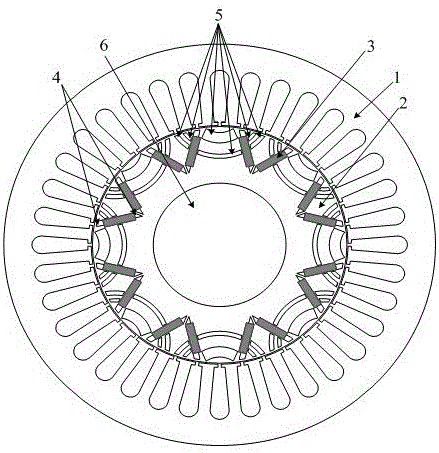
[0035] see figure 1 and figure 2 , the present invention includes a stator 1, a rotor 2, a rotating shaft 6 and an end cover 7, the stator 1 and the end cover 7 are fixedly connected together, and the end cover 7 is fixedly installed on the base 8. The rotor 2 is coaxially sleeved inside the stator 1 , and the rotating shaft 6 is coaxially fixed at the center of the rotor 2 . There is an air gap between the inner wall of the stator 1 and the outer wall of the rotor 2, and the thickness of the air gap is related to the power level of the motor, the selected permanent magnet material, and the processing and assembly process of the stator 1 and rotor 2. Both the stator 1 and the rotor 2 are formed by laminating silicon steel sheets with a thickness of 0.35 mm, and the lamination coefficient is 0.95. The rotating shaft 6 is composed of non-magnetic materials.

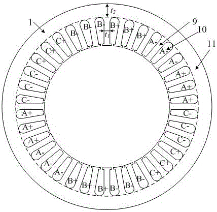
[0036] See 1 and image 3 , The stator 1 is composed of stator teeth 9 , stator slots 10 , and stator yoke 11 . A st...


PUM


Abstract

The invention discloses a built-in magnetic barrier type magnetic field enhanced permanent magnet brushless motor, comprising a stator and a rotor coaxially sleeved inside the stator. The rotor is evenly embedded with a plurality of pairs of permanent magnetic steels along the circumference, and each pair of the permanent magnetic steels are composed of two blocks of neodymium iron boron permanent steels of the same rectangular structure and placed in a V manner. The V-shaped opening faces an air gap and the adjacent two pairs of permanent magnetic steels are arranged symmetrically on the two sides of a cross axis; the inner part of the rotor between adjacent two pairs of permanent magnetic steels is provided with a first group of arc shaped built-in magnetic barriers whose arc openings face the air gap; a second group of arc shaped built-in magnetic barriers and a third group of arc shaped built-in magnetic barriers whose arc openings face the air gap and whose structures are identical and are symmetrically arranged around a straight axis are arranged between the two neodymium iron boron permanent steels of each pair of the permanent magnetic steels. Each group of the arc shaped built-in magnetic barriers contains an inner magnetic barrier and an outer magnetic barrier. The adjacent two pairs of permanent magnetic steels alternate for tangential magnetization, and the tangential magnetization directions of two blocks of neodymium iron boron permanent steels in each pair of the permanent magnetic steels are opposite to each other, which improves the driving performance and reliability of the motor.

Description

technical field [0001] The invention relates to a brushless permanent magnet synchronous motor, which belongs to the field of motor manufacturing and control, in particular to a motor suitable for applications such as driving motors for hybrid vehicles and electric vehicles, which can meet high efficiency, high power density and wide Drive performance requirements such as speed regulation. Background technique [0002] Vehicle drive motor is one of the key executive components of hybrid electric vehicles and electric vehicles, and the vehicle performance of hybrid electric vehicles and electric vehicles is closely related to the performance of drive motors. The traditional built-in permanent magnet brushless motor has the advantages of high efficiency and high power density, so it is widely used in the field of vehicle drive motors. Due to the use of rare earth permanent magnet steel as a single excitation source, traditional permanent magnet brushless motors are trapped in...

Claims


Application Information

Patent Timeline
IPC IPC(8): H02K29/00H02K21/14H02K21/02H02K1/27
CPCH02K1/276H02K21/028H02K21/14H02K29/00H02K2213/03
Inventor 朱孝勇杨深全力张超杜怿项子旋殷佳宁樊德阳吴文叶
Owner SUMEC HARDWARE & TOOLS
Why Eureka
Try Eureka