Ventilation structure

An air outlet and volute technology, applied in the field of ventilation equipment, can solve the problems of environmental noise pollution, strong noise, etc., and achieve the effects of reducing rotating noise, improving elimination efficiency, and reducing pulse force.

Inactive Publication Date: 2016-10-19
CHONGQING DONGHONGXIN TECH
View PDF0 Cites 0 Cited by
  • Summary
  • Abstract
  • Description
  • Claims
  • Application Information

AI Technical Summary

Problems solved by technology

[0004] However, the ventilation will also be accompanied by strong noise, which brings serious noise pollution to the environment.

Method used


Image

  • Ventilation structure
  • Ventilation structure
  • Ventilation structure

Examples


Embodiment 1

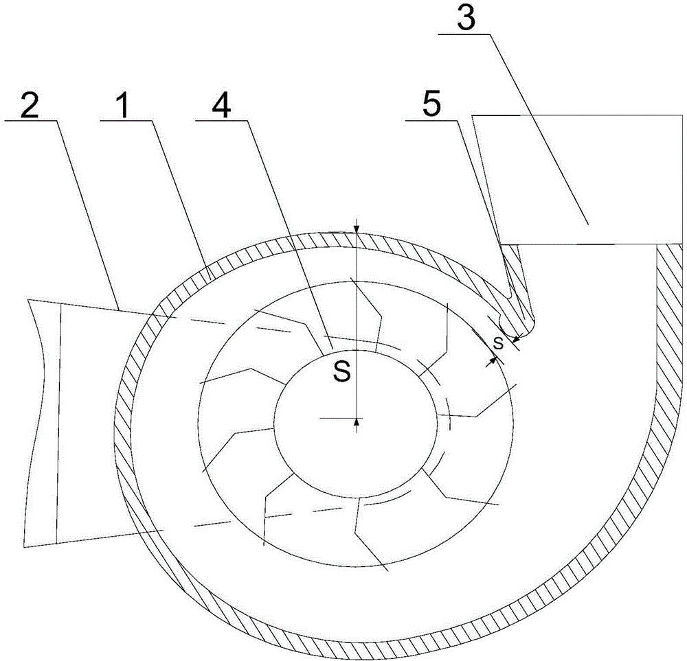
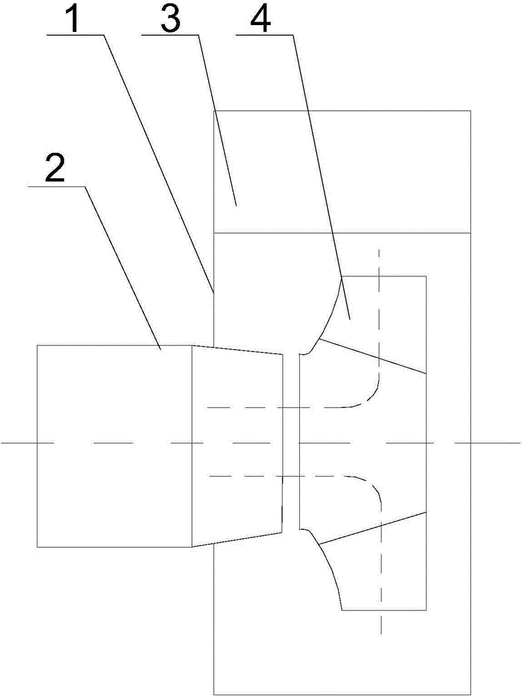
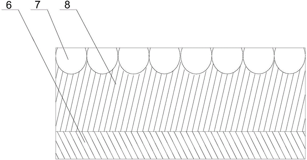
[0025] Such as Figure 1 to Figure 4As shown, this embodiment includes a volute 1 and an impeller 4 fixed in the volute 1, and the two sides of the volute 1 are respectively provided with a horizontal air inlet 2 and a vertical air outlet 3. A volute tongue 5 is arranged between the volute 1 and the air outlet 3, and the tongue tip of the volute 5 is inclined to the side close to the impeller 4, and the sound-absorbing cotton 8 is fixed on the inner wall of the volute 1 through the viscose layer 6, and on the The upper surface of the sound-absorbing cotton 8 is provided with a plurality of sound-absorbing blind holes 7 arranged side by side with a three-quarter circle longitudinal section; a sound-absorbing tube 9 is threadedly connected to the end of the air outlet 3, and a sound-absorbing tube 9 is threaded near the volute tongue. 5. A first muffler 10 is installed on one-half of the inner wall of the muffler cylinder 9 on one side, and a second muffler 11 is fixed on the re...


PUM


Abstract

The invention discloses a ventilation structure comprising a spiral case and an impeller, and a second impeller; the impeller and the second impeller are staggered; a worm tongue is arranged between the spiral case and the air outlet; the worm tongue tip leans to the impeller; the air outlet end is screwed by a denoising barrel; the 1 / 2 inner wall, close to the worm tongue, of the denoising barrel is provided with a first denoising sponge; the rest 1 / 2 inner wall of the denoising barrel is fixedly provided with a second denoising sponge; the distance between the highest point of the first denoising sponge and the denoising barrel inner wall is A; the distance between the highest point of the second denoising sponge and the denoising barrel inner wall is B, and A>B. The first denoising sponge can denoise high db rotation noises formed by fast airflow and the worm tongue; the second denoising sponge can denoise low db rotation noises; airflow layers of different speeds in the spiral case can be differentially treated, thus ensuring airflow in the air outlet to quietly and stably output.

Description

technical field [0001] The invention relates to ventilation equipment, in particular to a ventilation structure. Background technique [0002] The centrifugal fan is mainly composed of: impeller, casing, coupling and shaft. The impeller is the main working part that generates wind pressure and transmits energy; the casing is mainly used to introduce gas and discharge gas, and at the same time convert part of the kinetic energy of the gas into pressure energy; the coupling is used to connect the motor and fan to transmit torque; the shaft is installed and Fixed impeller, through coupling and motor. [0003] When the impeller rotates, the gas between the blades of the centrifugal fan is subjected to centrifugal force to obtain kinetic energy (dynamic pressure head) and is discharged from the periphery of the impeller, guided by the volute-shaped casing, so that it flows to the outlet of the fan, so that it flows in the center of the impeller. Negative pressure is formed, so ...

Claims


Application Information

Patent Timeline
IPC IPC(8): F04D29/66F04D29/42
Inventor 彭君秀
Owner CHONGQING DONGHONGXIN TECH
Why Eureka
Try Eureka