Supercharge Your Innovation With Domain-Expert AI Agents!

A Pyramid Horn Antenna Loaded with a Metal Grid and Its Design Method

A technology of horn antenna and metal grid, which is applied in the direction of antenna, waveguide horn, electrical components, etc., can solve the problem of increasing the volume of the antenna, and achieve the effect of improving the gain of the antenna and good directivity

Active Publication Date: 2019-01-15
UNIV OF ELECTRONICS SCI & TECH OF CHINA
View PDF3 Cites 0 Cited by
  • Summary
  • Abstract
  • Description
  • Claims
  • Application Information

AI Technical Summary

Problems solved by technology

But the dielectric lens will increase the volume of the antenna while optimizing the performance of the antenna

Method used


Image

  • A Pyramid Horn Antenna Loaded with a Metal Grid and Its Design Method
  • A Pyramid Horn Antenna Loaded with a Metal Grid and Its Design Method
  • A Pyramid Horn Antenna Loaded with a Metal Grid and Its Design Method

Examples


Embodiment Construction

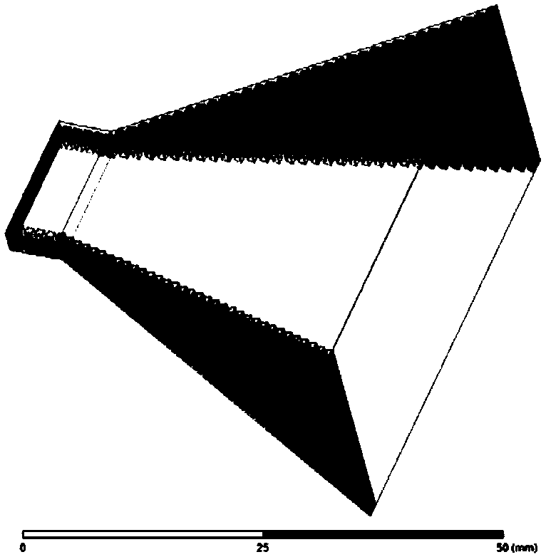
[0024] Taking the SIW pyramidal antenna as an example, the technical solution of the present invention is described in detail in conjunction with the accompanying drawings.

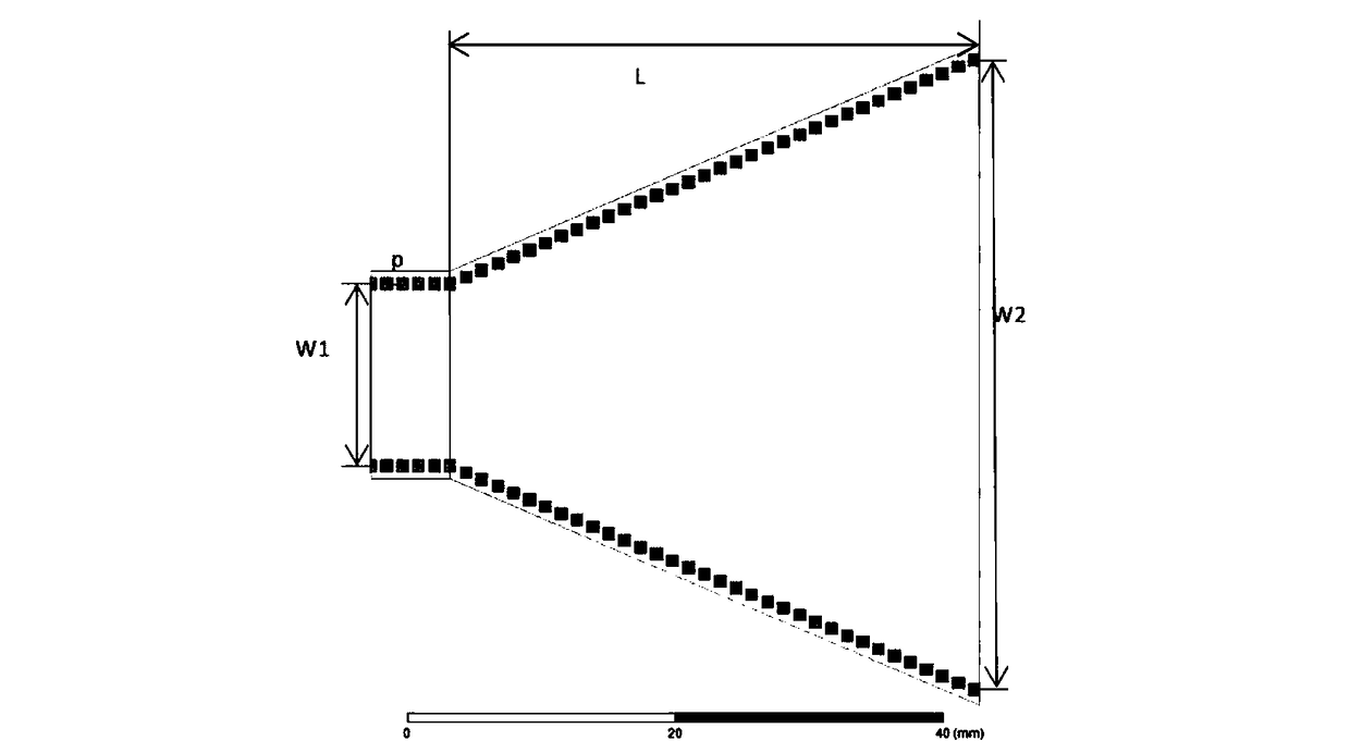
[0025] Step 1. Select the X-band SIW pyramid horn antenna such as figure 1 . The side length of the square through hole is d=0.8mm, and the distance between adjacent metal through holes is p=1.4mm. The thickness of the SIW at the throat of the antenna is b1=2.8mm, and the distance between two rows of metal holes of the SIW transmission line is w1=13.8mm. The length of the pyramid part in the antenna is L=40mm, w2=47.6mm, b2=26mm. The parameters of the dielectric substrate are: the relative permittivity is 2.1, and the loss tangent is 0.001.

[0026] Step 2. Add a metal strip with a width of 0.1mm and a thickness of 0.01mm at the horn antenna port, which is equal to the height of the long side of the horn mouth and perpendicular to the E plane. According to the principle of the Fresnel lens and the empi...


PUM


Abstract

The invention belongs to the field of microwave communication, in particular to a pyramidal horn antenna loaded with a metal grid. The metal grid-loaded pyramid horn antenna includes a pyramid horn antenna and a metal grid. The metal grid is n metal strips arranged parallel to the aperture of the pyramid horn antenna, 6≤n≤12, the metal strip is perpendicular to the H surface side w2 of the aperture, and the metal strips on both sides of the perpendicular line on the aperture of w2 Symmetrical about the mid-perpendicular. The length TL of the metal strip is equal to the edge b2 of the aperture E, the width of the metal strip is 0.01mm≤TW≤(w2 / λ)mm, and the thickness is 0.01mm≤D≤TW. The distance between adjacent metal strips gradually changes from the middle to both sides. The invention provides a new lens form. By loading a metal grid on the caliber of the pyramidal horn antenna, the gain of the antenna is improved and better directivity is achieved. At the same time, the volume of the antenna is basically not increased and the processing process is simple.

Description

technical field [0001] The invention belongs to the field of microwave communication and relates to transmission line, lens and antenna technology. In particular, it relates to a pyramidal horn antenna loaded with a metal grid. Background technique [0002] As one of the aperture surface antennas, the pyramidal horn antenna itself has the advantages of wide frequency band, low sidelobe, and simple structure. It is widely used in the field of microwave communication. Its main function is to generate uniform phase wavefront for better directivity. [0003] At the same time, the aperture of the pyramid antenna can increase the gain of the antenna and achieve better directivity by adding a lens to become a lens antenna. However, the dielectric lens will increase the volume of the antenna while optimizing the performance of the antenna. The study of new lenses is of great significance. Contents of the invention [0004] Aiming at the present situation above, the present inv...

Claims


Application Information

Patent Timeline
Patent Type & Authority Patents(China)
IPC IPC(8): H01Q13/02H01Q19/08
CPCH01Q13/02H01Q19/08
Inventor 陈良梁新鹏汪晓光邓龙江梁迪飞李丽华董师伶
Owner UNIV OF ELECTRONICS SCI & TECH OF CHINA
Features
  • R&D
  • Intellectual Property
  • Life Sciences
  • Materials
  • Tech Scout
  • Unparalleled Data Quality
  • Higher Quality Content
  • 60% Fewer Hallucinations
Learn More