

Power generating device, controller and switching system
A power generation device and controller technology, which is applied in the field of controllers, switch systems, and power generation devices, can solve the problems of unable to meet the power supply requirements of electrical equipment and large volume of power generation devices, and achieve reduced configuration costs, simple structure, and no environmental pollution Effect
- Summary
- Abstract
- Description
- Claims
- Application Information
AI Technical Summary
Problems solved by technology
Method used
Image

Examples
Embodiment 1
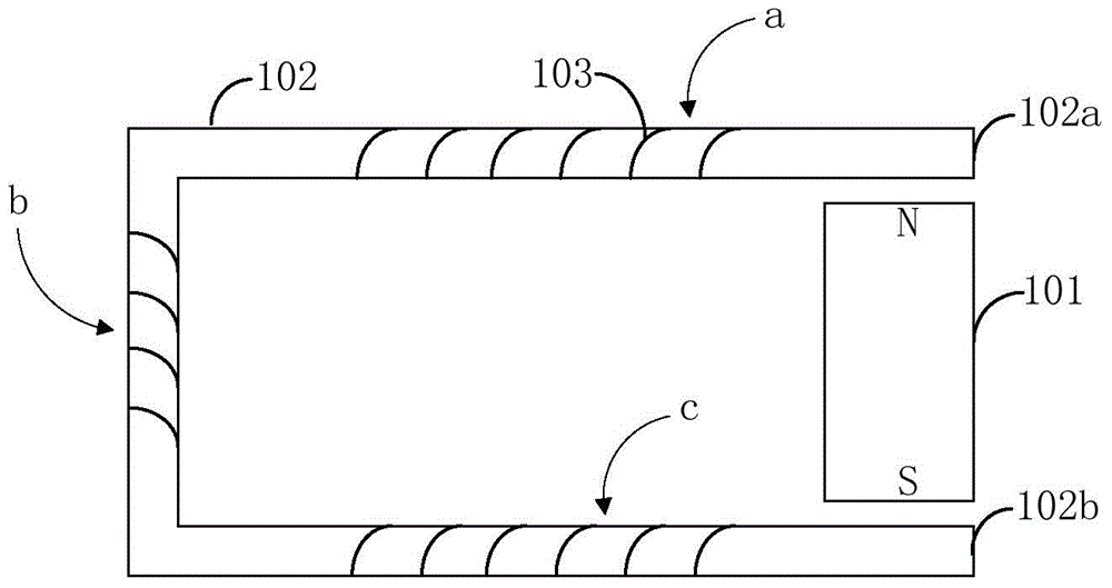
[0052] figure 1A schematic structural diagram of the power generating device provided by this embodiment is shown.
[0053] Such as figure 1 As shown, the power generation device provided by this embodiment includes a magnet member 101 , a magnetizer 102 and a power generation coil 103 . Wherein, the magnet member 101 is used to generate a stable magnetic field, and the generator coil 103 is fixed around the magnetizer 102 . When the magnetizer 102 and / or the magnet component 101 moves under the action of an external force, relative movement occurs between the magnet component 101 and the magnetizer 102 . Since the generator coil 103 is fixed on the magnetizer 102, when there is relative movement between the magnetizer 102 and the magnet member 101, there will also be a relative movement between the generator coil 103 and the magnet member 101, which also leads to passing through the magnet member 101. The magnetic flux of the coil 103 changes, so that the generating coil 1...
Embodiment 2
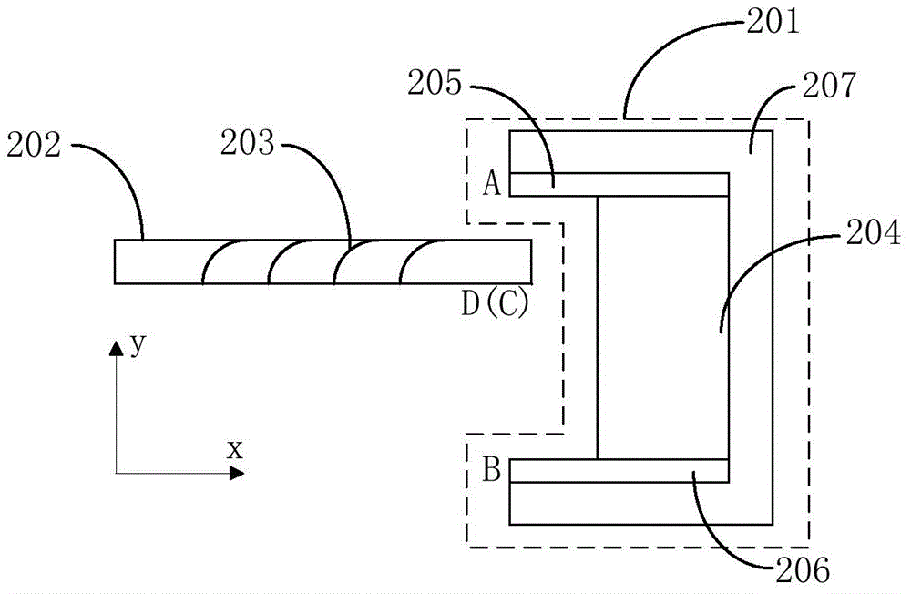
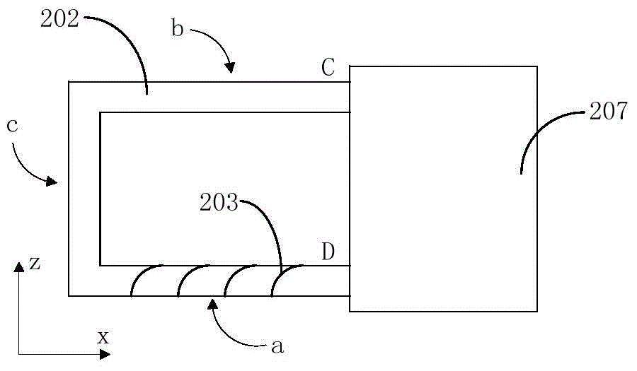
[0062] figure 2 and image 3 A front view and a top view of the power generating device provided by this embodiment are respectively shown.
[0063] Such as figure 2 As shown, the power generation device provided in this embodiment includes a magnet member 201 , a magnetizer 202 and a generator coil 203 wound on the magnetizer 202 . Wherein, the magnet member 201 is a "U" shape, including a first magnet end (ie end A) and a second magnet end (ie end B), and the first magnet end and the second magnet end extend outward from the main body of the magnet member 201 , thus forming a "U" word structure. One end (ie end C and end D) of the magnetizer 202 partially extends into the gap between the first magnet end and the second magnet end.
[0064] In this embodiment, the magnet member 201 includes a permanent magnet 204 , a first magnetic field converging part 205 and a second magnetic field converging part 206 . Wherein, the first magnetic field converging part 205 is in con...
Embodiment 3
[0079] Figure 6 A schematic structural diagram of the power generating device provided by this embodiment is shown.
[0080] Such as Figure 6 As shown, compared with the power generation device shown in Embodiment 2, the power generation device provided in this embodiment includes two magnet components (namely the first magnet component 301 and the second magnet component 302), a magnetizer 303 and a The generator coil 304 on the magnetizer 303. The structure of the first magnet component 301 and the second magnet component 302 is the same as that of the magnet component 201 shown in the second embodiment, and will not be repeated here.
[0081] From Figure 6 It can be seen that in this embodiment, the first magnet component 301 is placed opposite to the second magnet component 302 , and the magnetizer 303 is placed between the first magnet component 301 and the second magnet component 302 . One end (such as end G) of the magnetizer 303 extends into the gap between the en...
PUM
 Abstract
Description
Claims
Application Information