Low-power consumption power-on reset circuit

A technology of electric reset and low power consumption, which is applied in the field of low power power-on reset circuit, can solve the problems of reset signal generation, low power consumption, static power consumption, etc., and achieve the effect of strong anti-interference ability and low power consumption

Active Publication Date: 2016-10-19
SHANGHAI BEILING
View PDF7 Cites 14 Cited by
  • Summary
  • Abstract
  • Description
  • Claims
  • Application Information

AI Technical Summary

Problems solved by technology

The capacitor-resistance structure uses the time constant of the capacitor-resistance product as a delay to generate a reset signal. The advantage is that it does not consume power after the power-on process is over. The disadvantage is that it cannot generate a reset signal during the slow power-on process; the level-triggered structure combines the power supply voltage with Compared with the set voltage, when the power supply voltage is higher than the set voltage, the power-on reset signal is released. The advantage is that the reset signal has nothing to do with the power-on speed, and the disadvantage is that it needs to consume static power
Therefore, there is a lack of a low-power power-on reset circuit, which can not only have the advantages of a level-triggered structure, but also have lower power consumption.

Method used


Image

  • Low-power consumption power-on reset circuit
  • Low-power consumption power-on reset circuit
  • Low-power consumption power-on reset circuit

Examples


Embodiment Construction

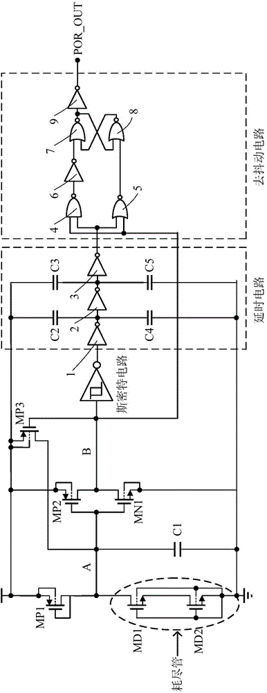
[0026] The structure and working principle of the low-power power-on reset circuit of the present invention will be described in detail below in conjunction with the accompanying drawings. Such as figure 1 As shown, in this embodiment, the power-on reset circuit includes a power-on reset signal generation circuit, a Schmidt circuit, a delay circuit and a debounce circuit that are connected to each other.

[0027] Specifically, the power-on reset signal generation circuit includes two branches connected in parallel, the first branch includes a first PMOS transistor MP1, its source is connected to the power supply, the gate is short-circuited to the drain, and the drain is connected to the first power consumption The drain of the depletion-type NMOS transistor MD1 is connected, the source of the first depletion-type NMOS transistor MD1 is connected to the drain of the second depletion-type NMOS transistor MD2, and the source of the second depletion-type NMOS transistor MD2 is gr...


PUM


Abstract

The invention discloses a low power consumption power-on reset circuit, comprising two branches which are connected in parallel; a first branch comprises a first PMOS transistor, a first depletion type MOS transistor and a second depletion type MOS transistor; the source electrode of the first PMOS transistor is connected to a power supply; a grid is in short circuit connection with a drain electrode; the drain electrode of the first depletion type MOS transistor is connected to the drain electrode of the first PMOS transistor, and the node between the MOS transistor and the PMOS transistor is used as a first node; a first capacitor is connected between the first node and the ground; a second branch comprises a second PMOS transistor and a first NMOS transistor which are in parallel connection with a common grid; the source electrode of the second PMOS transistor is connected to the power supply; the drain electrode is connected to the drain electrode of the first NMOS transistor; the node between the second PMOS transistor and the first NMOS transistor is used as a second node for outputting a first reset signal; the lower-power consumption power-on reset circuit also comprises a third PMOS transistor; the third PMOS transistor is used for locking voltage of the first node according to a first reset signal. The low-power consumption power-on reset circuit adopts an electrical level triggering mode to generate a reset signal, has advantages of low power consumption and a strong anti-interference capability and compensates insufficiency in the current technology.

Description

technical field [0001] The invention relates to a low power consumption power-on reset circuit. Background technique [0002] When the chip is powered on, a reset signal needs to be generated to reset the internal registers. Commonly used power-on reset circuits include capacitor-resistor structures and level-triggered structures. The capacitor-resistance structure uses the time constant of the capacitor-resistance product as a delay to generate a reset signal. The advantage is that it does not consume power after the power-on process is over. The disadvantage is that it cannot generate a reset signal during the slow power-on process; the level-triggered structure combines the power supply voltage with Compared with the set voltage, when the power supply voltage is higher than the set voltage, the power-on reset signal is released. The advantage is that the reset signal has nothing to do with the power-on speed, and the disadvantage is that it needs to consume static power c...

Claims


Application Information

Patent Timeline
Patent Type & Authority Applications(China)
IPC IPC(8): H03K17/22
Inventor 李鹏秦毅丁学欣
Owner SHANGHAI BEILING
Why Eureka
Try Eureka