Multi-shaft mixer for materials of high viscosity or low viscosity

A mixer and viscous technology, which is applied in mixers, mixers, chemical/physical processes and other directions with rotating mixing devices, can solve problems such as uniform mixing of non-viscous materials, product quality decline, and product quality impact, and achieve shortened time. The effect of mixing time, improving product quality, and preventing wall hanging

Inactive Publication Date: 2016-10-26
无锡意凯自动化技术有限公司
View PDF7 Cites 0 Cited by
  • Summary
  • Abstract
  • Description
  • Claims
  • Application Information

AI Technical Summary

Problems solved by technology

[0002] Vacuum homogeneous emulsifier has been widely used as an important processing equipment for daily chemical food. There is a big difference between the stirring of viscous materials and the stirring of ordinary solutions. The stirring of viscous materials is easy to stir air into the viscous materials. Granular impurities appear in the viscous material during stirring, which affects the quality of the product. Generally, the agitator used for viscous materials mostly uses impeller or screw mixers, because this type of mixer is easy to form in the state of high-speed rotation. Eddy current, it is easy to inject air to make the material react with the air, and it is not easy to mix a large amount of viscous material evenly, and relying on blindly increasing the speed of the stirring paddle will cause excessive energy consumption and decline in product quality

Method used


Image

  • Multi-shaft mixer for materials of high viscosity or low viscosity
  • Multi-shaft mixer for materials of high viscosity or low viscosity

Examples


Embodiment Construction

[0013] The technical solutions of the present invention will be described in detail below, but the protection scope of the present invention is not limited to the embodiments.

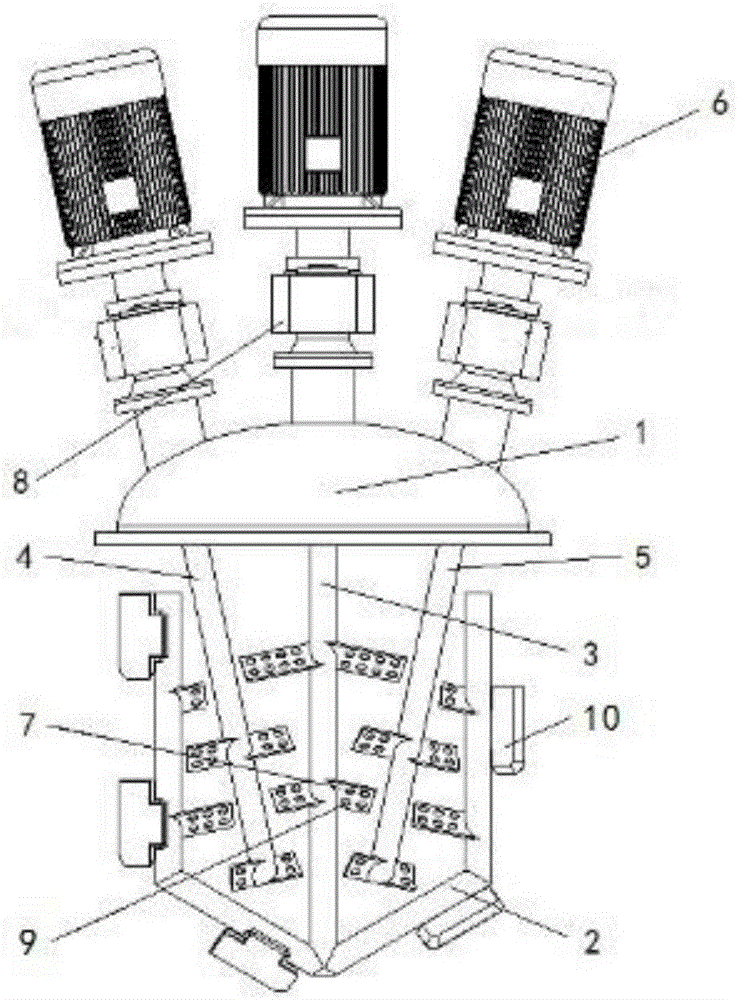
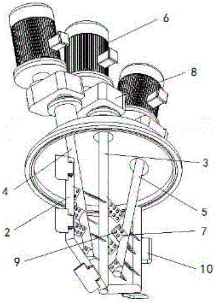
[0014] Such as figure 1 and figure 2 As shown, a multi-axis mixer for high and low viscosity materials includes a machine cover 1, a U-shaped stirring paddle 2, a first straight paddle 3, a second straight paddle 4, a third straight paddle 5, a reducer 8 and The motor 6, the transmission ends of the first straight stirring paddle 3, the second straight stirring paddle 4 and the third straight stirring paddle 5 respectively pass through the machine cover 1 and are fixed on the bearing seat. The opening of the U-shaped stirring paddle 2 is vertically arranged on the Right below the machine cover 1, the upper opening of the U-shaped stirring paddle 2 reduces the degree of tumbling of the upper layer of the material and prevents air from being involved in the material and causing deterioration. The angle...


PUM

PropertyMeasurementUnit
Diameteraaaaaaaaaa
Angleaaaaaaaaaa

Abstract

The invention discloses a multi-shaft mixer for materials of high viscosity or low viscosity. The multi-shaft mixer comprises a cover, a U-shaped stirring paddle, a first straight stirring paddle, a second straight stirring paddle, a third straight stirring paddle, speed reducers and motors, wherein the driving ends of the first straight stirring paddle, the second straight stirring paddle and the third straight stirring paddle respectively penetrate through the cover; the opening in the U-shaped stirring paddle faces upward vertically, and is right under the cover; the center in the bottom of the U-shaped stirring paddle is fixedly connected with the bottom of the first straight stirring paddle; stirring blades of the U-shaped stirring paddle, the first straight stirring paddle, the second straight stirring paddle and the third straight stirring paddle are arranged in a staggered manner, while every two adjacent stirring blades are on different planes. Therefore, according to the multi-shaft mixer, the stirring direction of a material is changed constantly; the material is stirred and cut in layers; the mechanical homogeneous strength of the viscous material is enhanced; the stirring time is shortened; equipment energy consumption is reduced; the product quality is improved.

Description

technical field [0001] The invention relates to a mixer, in particular to a mixer for viscous materials. Background technique [0002] Vacuum homogeneous emulsifier has been widely used as an important processing equipment for daily chemical food. There is a big difference between the stirring of viscous materials and the stirring of ordinary solutions. The stirring of viscous materials is easy to stir air into the viscous materials. Granular impurities appear in the viscous material during stirring, which affects the quality of the product. Generally, the impeller or screw mixer is used for the stirring paddle of the viscous material, because this kind of mixer is easy to form in the state of high-speed rotation. The vortex is easy to inject air to make the material react with the air, and it is not easy to mix a large amount of viscous material evenly, and relying on blindly increasing the speed of the stirring paddle will cause excessive energy consumption and decline in ...

Claims


Application Information

Patent Timeline
IPC IPC(8): B01F7/04B01F3/08
CPCB01F23/41B01F27/706B01F2101/06
Inventor 张盛雄
Owner 无锡意凯自动化技术有限公司
Why Eureka
Try Eureka