Pouring section line body of iron mould sand coating production line

A technology of sand-covering and pouring sections of iron molds, which is applied to the equipment for feeding molten metal into molds, metal processing equipment, casting equipment, etc., and can solve the problems of iron mold cavity vibration damage, unstable transfer process, side roller frame Deformation and other problems, to achieve the effect of stable operation, increased practicability, and smooth transfer

Active Publication Date: 2016-10-26
山西东鑫衡隆机械制造股份有限公司
View PDF4 Cites 3 Cited by
  • Summary
  • Abstract
  • Description
  • Claims
  • Application Information

AI Technical Summary

Problems solved by technology

[0005] The technical problem to be solved by the present invention is to overcome the above-mentioned deficiencies, and provide a casting section line body of the iron mold sand-coated production line, which solves the problem of long-term unilateral load bearing, deformation of the side roller frame, and unstable transfer process, resulting in vibration damage to the iron mold cavity. problems, and the entire iron mold sand-coated production line moves smoothly and reliably, which not only greatly reduces the labor intensity of workers, but also ensures the consistency of casting quality, effectively improving the high tensile strength and high elongation of castings

Method used


Image

  • Pouring section line body of iron mould sand coating production line
  • Pouring section line body of iron mould sand coating production line
  • Pouring section line body of iron mould sand coating production line

Examples


Embodiment Construction

[0030] In order to enable those skilled in the art to better understand the purpose, technical solutions and advantages of the present invention, the present invention will be further described in detail below in conjunction with the accompanying drawings. It should be understood that the specific embodiments described here are only used to explain the present invention, not to limit the present invention.

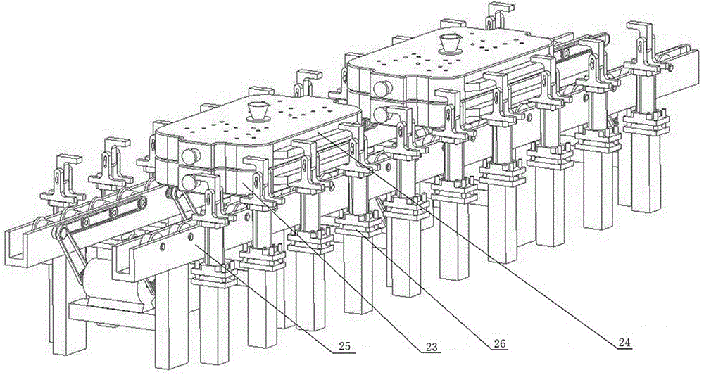
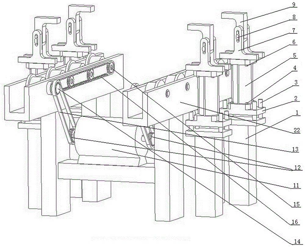
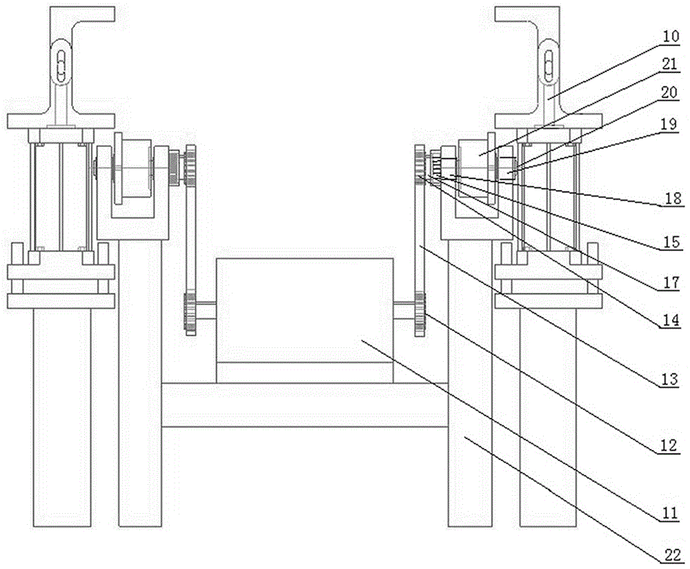
[0031] A cast section line body of an iron mold sand-covered production line, such as figure 1 , figure 2 , image 3 , Figure 4 As shown, it includes an automatic roller table device 25, a clamping device 26 and an integrated system for automatic control of the pouring line body.

[0032] The clamping device 26 includes a clamping base 1, a connecting piece 2, a guide pin 3, a first bolt 6, a second bolt 4, a pneumatic cylinder 5, an upper clamping buckle 9, a lower clamping buckle 7 and a guide key 8, The clamping base 1 is provided with a fixed guide pin 3, and the...


PUM


Abstract

The invention relates to a pouring section line body of an iron mould sand coating production line. The pouring section line body comprises an automatic roller bed device, a clamping device and a pouring section line body automatic control integration system. During work, the automatic roller bed device is controlled through the pouring section line body automatic control integration system, and iron moulds which are coated with sand cavities are sequentially transferred to pouring positions; before castings are poured, upper iron moulds and lower iron moulds are firmly clamped through the clamping device, so that the internal textures of the castings are compact during the mould filing process of the castings; and after the castings are cooled, the clamping device loosens, and the iron moulds are transferred to a demoulding process by controlling the automatic roller bed device, so that the castings are taken out. By adopting the pouring section line body, the problem of vibration damage to iron mould cavities caused by long-term unilateral load bearing, deformation of side roller racks and instability during transferring processes is solved; movement of the whole iron mould sand coating production line is stable and reliable; labor intensity of workers is greatly lowered, and consistency of quality of castings can be ensured; and tension-resistance and ductility of the castings can be effectively improved.

Description

technical field [0001] The invention belongs to casting equipment, in particular to a pouring section of an iron mold sand-covered production line. Background technique [0002] In the foundry industry, the iron mold sand-coated process is used to produce ductile iron castings. The excellent performance of the products has been widely recognized by the industry. It is the guarantee to realize the lightweight of castings and the realization of replacing steel with iron. [0003] The sand-covered iron mold process produces ductile iron products. During the casting process, the molten iron will be spheroidized and inoculated. The molten iron is poured into the iron mold. Before it is completely solidified, the graphite balls formed inside the molten iron will undergo an expansion process. Here stage, the expansion force will promote the upper iron mold and the lower iron mold to separate them in reverse. If during this process, the clamping force is applied to force the upper ...

Claims


Application Information

Patent Timeline
Patent Type & Authority Applications(China)
IPC IPC(8): B22D35/04
CPCB22D35/04
Inventor 张强强王刚刚王海龙陈宝生
Owner 山西东鑫衡隆机械制造股份有限公司
Why Eureka
Try Eureka