Gas atomization powder production equipment and powder production method thereof

A pulverizing equipment and gas atomization technology, which are applied in the field of metal powder manufacturing, can solve the problems of high consumption of atomized gas flow, increase the cost and high cost of gas atomized metal powder, and achieve the improvement of quality, utilization rate and production efficiency. , the effect of reducing costs

Active Publication Date: 2016-10-26
浙江天钛增材制造技术有限公司
View PDF5 Cites 19 Cited by
  • Summary
  • Abstract
  • Description
  • Claims
  • Application Information

AI Technical Summary

Problems solved by technology

Under the same atomizing gas flow rate, the larger the aperture, the greater the atomizing gas flow

Method used


Image

  • Gas atomization powder production equipment and powder production method thereof

Examples


Embodiment 1

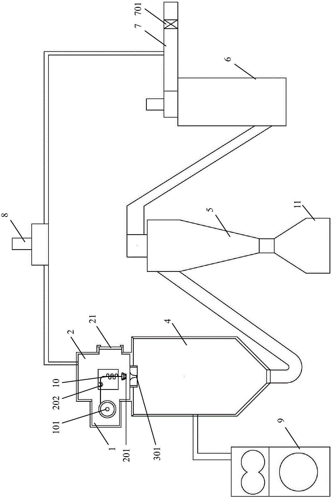
[0050] like figure 1 As shown, a gas atomization powder making equipment includes a raw material bin 1 , a melting chamber 2 , an atomizer, an atomization tower 4 , a cyclone separator 5 , and a vacuum system 9 . Wherein, the raw material bin 1 is a vacuum-sealed structure, and a rotating bracket 101 for placing a metal wire tray is arranged therein. The smelting chamber 2 communicates with the raw material bin 1 and is integrated with the raw material bin 1, and the two are sealed and isolated from the outside world. The melting chamber 2 is a vacuum-sealed double-layer water-cooled structure, with an observation window 21 on the side to monitor the melting and atomization process. The observation window 21 is preferably made of quartz glass and can be equipped with a movable shading plate.

[0051]The melting chamber 2 is provided with an induction coil 201 and a wire feeder 202 that guides the wire on the rotating bracket into the upper center of the induction coil 201. In...

Embodiment 2

[0064] like figure 1 As shown, a gas atomization powder making equipment includes a raw material bin 1, a smelting chamber 2, an atomizer, an atomization tower 4, a cyclone separator 5, a tail filter 6, an exhaust pipe 7, and an internal circulation fan 8 and vacuum system9. Wherein, the raw material bin 1 is a vacuum-sealed structure, and a rotating bracket 101 for placing a metal wire tray is arranged therein. The smelting chamber 2 communicates with the raw material bin 1 and is integrated with the raw material bin 1, and the two are sealed and isolated from the outside world. The melting chamber 2 is a vacuum-sealed double-layer water-cooled structure, with an observation window 21 on the side to monitor the melting and atomization process. The observation window 21 is preferably made of quartz glass and can be equipped with a movable shading plate.

[0065] The melting chamber 2 is provided with an induction coil 201 and a wire feeder 202 that guides the wire on the rot...


PUM

PropertyMeasurementUnit
Diameteraaaaaaaaaa

Abstract

The invention discloses gas atomization powder production equipment and a powder production method thereof and belongs to the technical field of metal powder production. The gas atomization powder production equipment is characterized in that a rotary support rack for placing a metal wire material plate is arranged in the raw material bin of the powder production equipment; a smelting chamber is communicated with the raw material bin and provided with an induction coil and a wire feeder inside, and the wire feeder is used for guiding metal wire on the rotary support rack into a positon above the center of the induction coil; an atomizer is connected with the smelting chamber, and the upper-end opening of the atomizing nozzle of the atomizer faces the induction coil; an atomizing tower is connected with a cyclone separator, and the top of the atomizing tower is connected with the atomizer; a vacuum system is connected with the atomizing tower. The powder production equipment and the powder production method thereof have the advantages that the bar-shaped raw material is replaced by the metal wire, the utilization rate and production efficiency of atomizing gas are increased, and cost of gas atomization powder production is lowered; small liquid drops can obtain high superheat degree favorably, and the fine powder content in the atomized powder is increased.

Description

technical field [0001] The invention relates to the technical field of metal powder manufacturing, in particular to a gas atomization powder making equipment and a powder making method thereof. Background technique [0002] Due to the advantages of good fluidity and stable bulk density, spherical metal powder has become an essential raw material and consumable for metal 3D printing, surface cladding, spraying, metal injection molding and other fields. The use of gas atomization technology to manufacture spherical metal powder has become one of the methods commonly used in industry, especially for the field of spherical metal powder manufacturing of titanium, zirconium and their alloys. At present, the commonly used technology is to melt the raw material rods with high-frequency conical coils and induction heating without crucibles to form continuous or semi-continuous droplets, and then use high-pressure gas to produce spherical metal and alloy powders through gas atomizing ...

Claims


Application Information

Patent Timeline
IPC IPC(8): B22F9/08
CPCB22F9/082
Inventor 赵文天赵枫马旭东
Owner 浙江天钛增材制造技术有限公司
Why Eureka
Try Eureka