Novel continuous spot welding device

A spot welding device and a new type of technology, applied in welding equipment, resistance welding equipment, resistance electrode holders, etc., can solve the problems of high product defect rate, high manual operation intensity, high production cost, etc., to improve processing accuracy and production efficiency, The effect of reducing the intensity of manual operation and avoiding the failure of welding work

Inactive Publication Date: 2016-10-26
章勤正
View PDF0 Cites 3 Cited by
  • Summary
  • Abstract
  • Description
  • Claims
  • Application Information

AI Technical Summary

Problems solved by technology

[0002] Spot welding is usually divided into two categories: double-sided spot welding and single-sided spot welding. Spot welding is a high-speed and economical connection method. It is suitable for manufacturing stampings that can use lap joints, do not require airtight joints, and have a thickness of less than 3mm. 1. The rolled thin plate member is to weld the individual points of the weldment on the contact surface of the joint. The spot welding machine adopts the principle of double-sided double-point overcurrent welding. When working, the two electrodes press the workpiece to make the two layers of metal A certain contact resistance is formed under the pressure of the two electrodes, and when the welding current passes through the other electrode from one electrode to form an instant thermal fusion at the two contact resistance points, it is widely used in construction machinery repair, auto parts, electronic components, In the manufacturing industry of metal products such as metal packaging, the existing spot welding equipment is single-point welding, which needs to be manually transported and installed among multiple spot welding machines. The manual operation is intensive, the production cycle is long, and the production cost of the enterprise is high; Due to inaccurate positioning of the equipment, it is easy to cause welding work failure due to welding position deviation, high product defect rate, and serious waste of raw materials

Method used


Image

  • Novel continuous spot welding device

Examples


Embodiment Construction

[0012] The following will clearly and completely describe the technical solutions in the embodiments of the present invention with reference to the accompanying drawings in the embodiments of the present invention. Obviously, the described embodiments are only some, not all, embodiments of the present invention. Based on the embodiments of the present invention, all other embodiments obtained by persons of ordinary skill in the art without creative work all belong to the protection scope of the present invention.

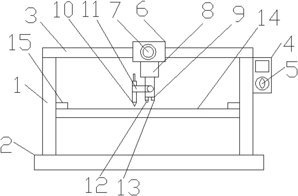
[0013] see figure 1 , the present invention provides a technical solution: a new type of continuous spot welding device, including a device main body 1, a base 2, a sliding guide rail 3, a control handle 4, an operating knob 5, a sliding device 6, a clamping knob 7, and a telescopic device 8 , telescopic rod 9, spot welding device 10, connecting rod 11, infrared transmitter 12, infrared receiver 13, workbench 14 and limit baffle 15, device main body 1 lower side is ...


PUM

PropertyMeasurementUnit
thicknessaaaaaaaaaa

Abstract

The invention discloses a novel continuous spot welding device, which comprises a device main body, a base, a sliding guide rail, a control handle, an operating knob, a sliding device, a clamping knob, a telescopic device, a telescopic rod, a spot welding device, a connecting rod, and an infrared emission device. Device, infrared receiver, workbench and limit baffle, the underside of the main body of the device is provided with a base, the upper side of the main body of the device is provided with a sliding guide rail, the right side of the sliding guide rail is provided with a control handle, and the control handle The lower side is provided with an operating knob, the left side of the control handle is provided with a sliding device, the lower side of the sliding device is provided with a clamping knob, and the lower side of the sliding device is provided with a telescopic device. This new type of continuous spot welding device has the characteristics of simple operation and high degree of automation, which improves the processing accuracy. Infrared equipment is added to detect the placement position of the air-conditioning cover through the infrared equipment, so as to avoid welding work failure and product failure due to welding position deviation. The phenomenon of high production rate and serious waste of raw materials.

Description

technical field [0001] The invention relates to the field of welding technology, in particular to a novel continuous spot welding device. Background technique [0002] Spot welding is usually divided into two categories: double-sided spot welding and single-sided spot welding. Spot welding is a high-speed and economical connection method. It is suitable for manufacturing stampings that can use lap joints, do not require airtight joints, and have a thickness of less than 3mm. 1. The rolled thin plate member is to weld the individual points of the weldment on the contact surface of the joint. The spot welding machine adopts the principle of double-sided double-point overcurrent welding. When working, the two electrodes press the workpiece to make the two layers of metal A certain contact resistance is formed under the pressure of the two electrodes, and when the welding current passes through the other electrode from one electrode to form an instant thermal fusion at the two c...

Claims


Application Information

Patent Timeline
Patent Type & Authority Applications(China)
IPC IPC(8): B23K11/11B23K11/31B23K11/36
CPCB23K11/11B23K11/318B23K11/36
Inventor 章勤正
Owner 章勤正
Why Eureka
Try Eureka