Device and method for recovering cooling liquid for machining
A mechanical processing and recovery device technology, applied in metal processing equipment, metal processing machinery parts, manufacturing tools, etc., can solve the problem of metal impurities flying randomly, and achieve the effect of protecting the environment, reducing pollution, and good separation effect
- Summary
- Abstract
- Description
- Claims
- Application Information
AI Technical Summary
Problems solved by technology
Method used
Image

Examples
Embodiment 1
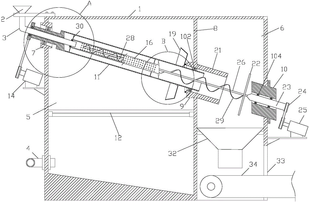
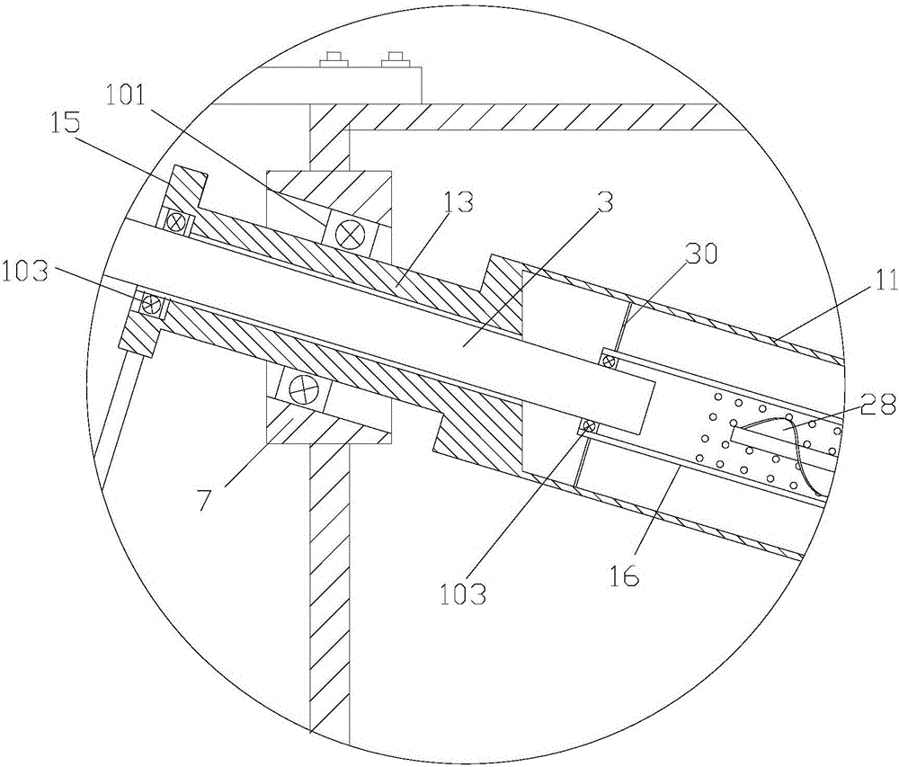
[0022] As shown in Figures 1, 2, and 3, the cooling liquid recovery device for machining described in this embodiment includes a housing 1, a liquid inlet hopper 2 at the front end of the housing 1, and a liquid inlet pipe 3 at the bottom of the liquid inlet hopper 2 and the liquid outlet pipe 4 on the housing 1; the housing 1 is divided into a front chamber 5 and a rear chamber 6 by a partition 8, and a front fixing seat 7 is provided on the front side wall of the front chamber 5, and the partition The plate 8 is provided with a central seat 9, and a rear fixed seat 10 is provided on the side wall of the rear end of the rear chamber 6, and the center of the front fixed seat 7, the central seat 9 and the rear fixed seat 10 are all provided with an oblique channel; The upper part of the front chamber 5 is provided with an inclined outer tube body 11, and the middle part of the front chamber 5 is provided with a filter screen 12; the outlet pipe 4 communicates with the lower part...
Embodiment 2
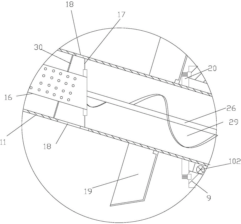
[0027] like Figure 4 As shown, the cooling liquid recovery device for mechanical processing described in this embodiment is different from that in Embodiment 1 in that the anti-splash and slag discharge pipe 21 is fixedly arranged on the rear side of the partition 8, and the anti-splash and slag discharge pipe 21 There is a bearing 27 between the outer tube body 11; the outlet of the outer tube body 11 is a bell mouth; when the metal impurities run to the bell mouth, they are subjected to oblique centrifugal force, so it is easy for the metal impurities to be thrown out, which is prevented from being thrown out again. The splashing slag discharge pipe 21 is blocked in time, so that the slag discharge efficiency is higher in this situation, and it is not easy to be blocked; obviously, the outer pipe body 11 may not be provided with a bell mouth;
[0028] The anti-splash and slag discharge pipe 21 is fixedly arranged on the partition plate 8 to realize connection, and a bearing...
Embodiment 3
[0030] The present invention also designs a cooling liquid recovery method for mechanical processing, which is characterized in that the cooling liquid produced by all mechanical processing equipment in the workshop is recovered and processed by a unified cooling liquid recovery device, and after the cooling liquid is separated by the cooling liquid recovery device Re-supply each machining equipment, and the cooling liquid recovery device is the cooling liquid recovery device for machining as described in the above embodiment 1 or 2.
[0031] The present invention also designs a cooling liquid recovery method for mechanical processing, and the cooling liquid is centrally processed, and the efficiency is higher.
PUM
 Abstract
Description
Claims
Application Information
 - Generate Ideas
- Intellectual Property
- Life Sciences
- Materials
- Tech Scout
- Unparalleled Data Quality
- Higher Quality Content
- 60% Fewer Hallucinations
Browse by: Latest US Patents, China's latest patents, Technical Efficacy Thesaurus, Application Domain, Technology Topic, Popular Technical Reports.
© 2025 PatSnap. All rights reserved.Legal|Privacy policy|Modern Slavery Act Transparency Statement|Sitemap|About US| Contact US: help@patsnap.com