A high-efficiency die-cutting device for release paper

A release paper and die-cutting technology, applied in the field of machinery, can solve the problems of high cost, high maintenance cost, limited use by small and medium-sized enterprises, etc., and achieve the effect of reducing replacement cost and convenient later maintenance.

Active Publication Date: 2018-06-26
北京英格条码技术发展有限公司
View PDF10 Cites 0 Cited by
  • Summary
  • Abstract
  • Description
  • Claims
  • Application Information

AI Technical Summary

Problems solved by technology

[0004] However, because the die-cutting machine is a relatively large-scale and precise mechanical product, it is expensive and the maintenance cost is high, which limits the use of some small and medium-sized enterprises.

Method used


Image

  • A high-efficiency die-cutting device for release paper
  • A high-efficiency die-cutting device for release paper
  • A high-efficiency die-cutting device for release paper

Examples


Embodiment 1

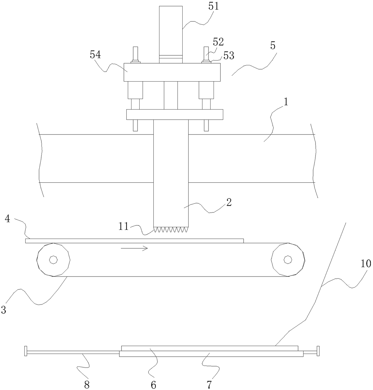
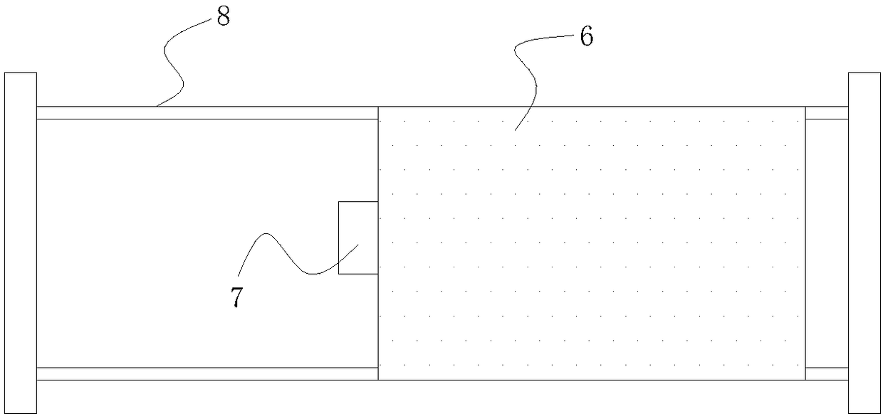
[0031] like figure 1 , image 3 as shown, figure 1 is a schematic diagram of the structure of the high-efficiency die-cutting device, image 3 It is a top view of the feeding mechanism.

[0032] A high-efficiency die-cutting device for release paper, comprising a die-cutting board 1 and a die-cutting knife cylinder 2, the die-cutting knife cylinder 2 runs through the die-cutting board 1 and the top and bottom ends of the die-cutting knife cylinder 2 are corresponding The upper and lower end faces of the die-cutting plate 1 protrude out, and the bottom of the die-cutting knife barrel 2 is equipped with a blade 11. The die-cutting device also includes a driving cylinder 5, a transmission mechanism 3 and a feeding mechanism,

[0033] The driving cylinder 5 is connected to the top of the die-cutting knife cylinder 2, and drives the die-cutting knife cylinder 2 to reciprocate up and down; the driving cylinder 5 includes a booster cylinder 51, a cylinder guide rod 52, a guide bas...

Embodiment 2

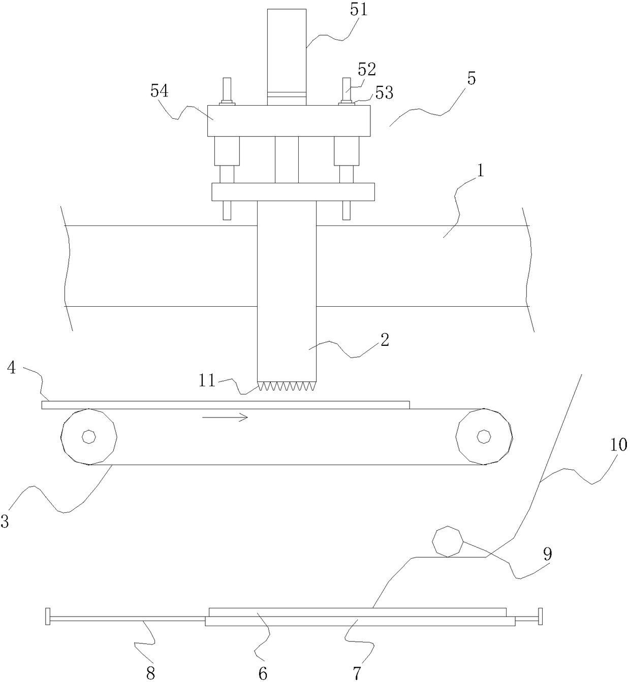
[0042] like figure 2 , image 3 as shown, figure 2 is a schematic diagram of the die-cutting device; image 3 It is a top view of the feeding mechanism.

[0043] A high-efficiency die-cutting device for release paper according to the embodiment of the present invention includes a die-cutting board 1 and a die-cutting knife cylinder 2, the die-cutting knife cylinder 2 runs through the die-cutting board 1 and the die-cutting knife cylinder 2 The top and bottom ends of the die-cutting plate 1 protrude from the upper and lower end surfaces of the die-cutting plate 1 accordingly, and the bottom of the die-cutting knife barrel 2 is equipped with a blade 11. The die-cutting device also includes a driving cylinder 5, a transmission mechanism 3 , auxiliary processing part 9 and feeding mechanism,

[0044]The driving cylinder 5 is connected to the top of the die-cutting knife cylinder 2, and drives the die-cutting knife cylinder 2 to reciprocate up and down; the driving cylinder 5...


PUM


Abstract

The invention relates to an efficient die cutting device for release paper. The efficient die cutting device comprises a die cutting plate and a die cutting tool cylinder. The die cutting tool cylinder penetrates the die cutting plate, and the top end and the bottom end of the die cutting tool cylinder stretch out of the upper end face and the lower end face of the die cutting plate correspondingly. A cutting edge is installed at the bottom of the die cutting tool cylinder. The die cutting device further comprises a drive cylinder, a transmission mechanism and a feeding mechanism. By means of the efficient die cutting device for the release paper, the die cutting efficiency of the die cutting device is high, the equipment is simplified, the size is reduced, cost is reduced, operation is simpler, and the efficient die cutting device is suitable for being used in small-sized or medium-sized enterprises.

Description

technical field [0001] The invention relates to a die-cutting device in the mechanical field, in particular to a high-efficiency die-cutting device for release paper. Background technique [0002] Die Cutting Machine (Die Cutting Machine) is also called beer machine, cutting machine or CNC stamping machine, mainly used for die cutting of some corresponding non-metallic materials, stickers, EVA, double-sided tape, electronics, mobile phone rubber pads, etc. (full break, half break), indentation and bronzing operations, lamination, automatic waste discharge, die-cutting machine uses steel knife, metal mold, steel wire (or template carved from steel plate), and exerts a certain pressure through the embossing plate , Cut the printed matter or cardboard into a certain shape. Products that have been die-cut by a die-cutting machine can be called film-cut products. [0003] Die-cut products generally include a layer of release paper, a protective layer and an adhesive layer betwe...

Claims


Application Information

Patent Timeline
Patent Type & Authority Patents(China)
IPC IPC(8): B26F1/44B26D5/12B26D7/06B26D7/32
CPCB26D5/12B26D7/0625B26D7/32B26D2007/322B26F1/44B26F2001/4418B26F2001/4472
Inventor 熊青李爱军
Owner 北京英格条码技术发展有限公司
Why Eureka
Try Eureka