Solder paste printer and printing method thereof

A solder paste printing machine and solder paste technology, which is applied to printing machines, rotary printing machines, screen printing machines, etc. Replacement is complicated and other problems, to achieve the effect of reducing manual intervention, facilitating replacement, and improving production flexibility

Active Publication Date: 2016-10-26
易视智瞳科技(深圳)有限公司
View PDF9 Cites 4 Cited by
  • Summary
  • Abstract
  • Description
  • Claims
  • Application Information

AI Technical Summary

Problems solved by technology

[0007] The main purpose of the present invention is to propose a solder paste printing machine and its printing method, which can solve the problems of inability to perform screen alignment on large-size printed circuit boards, partial printing of solder paste, and complicated screen replacement in the prior art. question

Method used


Image

  • Solder paste printer and printing method thereof
  • Solder paste printer and printing method thereof
  • Solder paste printer and printing method thereof

Examples


Embodiment 1

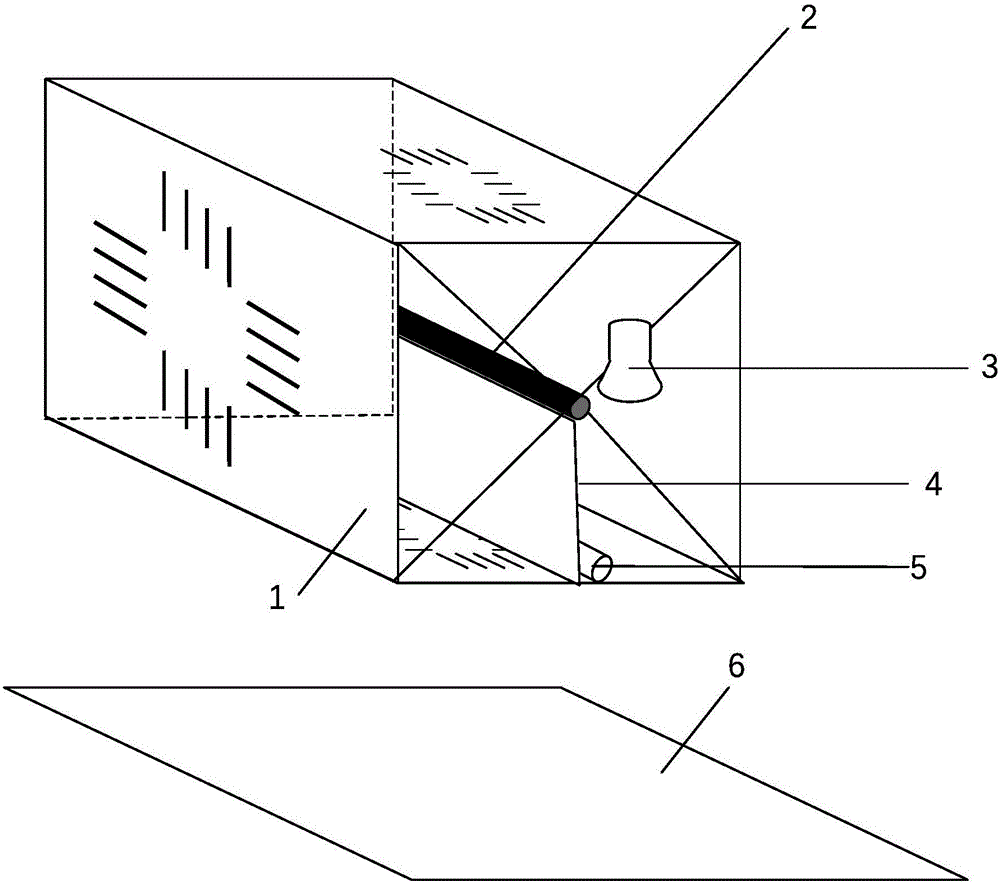
[0028] Please refer to figure 1 , Is a schematic diagram of the structure of the solder paste printer provided by the first embodiment of the present invention. The solder paste printer includes a screen group 1, a screen frame 2, a vision system 3, a solder paste scraper 4, a solder paste 5, and a printed circuit Board 6. Among them, the screen group 1 is fixed on the outer surface of the screen frame 2, the vision system 3 is fixed on the front end of the screen frame 2, and the solder paste scraper 4 and the solder paste 5 are located in the screen frame 2. Through the positioning of the working surface of the printed circuit board 6 by the vision system 3, the screen frame 2 drives the screen group 1, the solder paste scraper 4 and the solder paste 5 to the specified positions, and the solder paste scraper 4 passes the solder paste 5 through the screen group 1 is printed on the printed circuit board 6. After the printing is completed, the screen frame 2 is moved to the init...

Embodiment 2

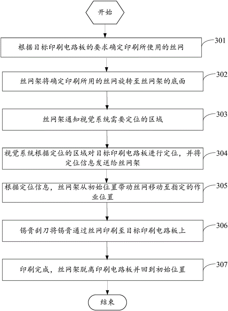
[0041] Please refer to image 3 The second embodiment of the present invention provides a solder paste printing method, which is implemented by the solder paste printer in the first embodiment, and the method includes the steps:

[0042] Step 301: Determine the screen used for printing according to the requirements of the target printed circuit board.

[0043] In step 302, the screen frame rotates the screen used for determining printing to the bottom surface of the screen frame.

[0044] Step 303: The screen frame informs the vision system of the area to be positioned.

[0045] Step 304: The vision system locates the target printed circuit board according to the location area, and sends the positioning information to the screen frame.

[0046] Step 305: According to the positioning information, the screen frame drives the screen from the initial position to move to the designated working position.

[0047] Step 306, the solder paste scraper screen prints the solder paste onto the target...

example 1

[0051] Example one is the case of partial solder paste printing on a large-size printed circuit board.

[0052] Please refer to Figure 4 , The printed circuit board 6 has a larger format and is divided into four areas for partial solder paste printing.

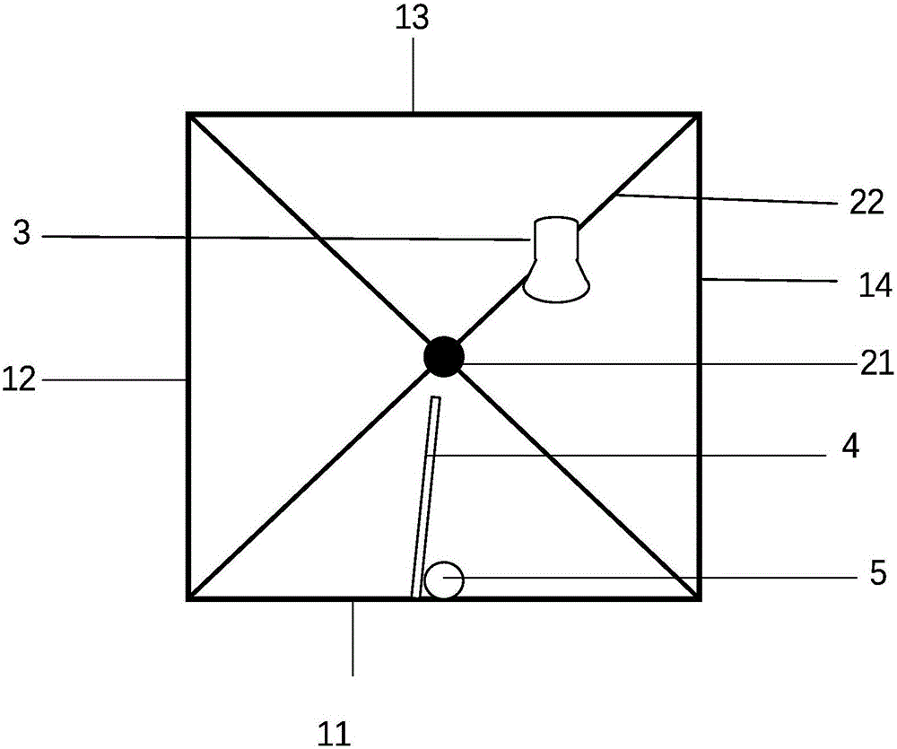
[0053] Specifically, the printed circuit board 6 is divided into areas 61, 62, 63, and 64 to be printed according to the requirements of the printing format, corresponding to the screens 11, 12, 13, 14 fixed on the screen frame 2 (such as figure 2 Shown).

[0054] The screen frame 2 is moved to the area to be printed 61, the screen 11 is determined to be used for printing, and the screen 11 is rotated to the bottom surface of the screen frame 2, and a signal is sent to notify the vision system 3 that the area to be positioned is the area 61.

[0055] The vision system 3 captures the image of the area 61 to be printed, locates the mark points, and transmits the positioning information to the controller of the screen frame 2.

[0056] T...


PUM


Abstract

The invention provides a solder paste printer and a printing method thereof, and belongs to the technical field of solder paste printing processes. The solder paste printer comprises a screen group, a screen frame, a visual system, a solder paste scraper, a solder paste and a printed circuit board, wherein the screen group comprises a plurality of screens, and the plurality of screens are distributed on a plurality of outer surfaces of the screen frame respectively; one of the screens is selected according to a breadth requirement of the printed circuit board, and is rotated to a working surface of the screen frame by the screen frame; the visual system is used for carrying out visual location on the screen group and the printed circuit board, and sending location information to the screen frame, so that the screen frame moves the screen to a working position needing printing; and the solder paste scraper is used for printing the solder paste onto the printed circuit board through the screen. The solder paste printer and the printing method thereof, which are provided by the invention, are applicable to local printing operation on large-dimension printed circuit boards and printed circuit boards of existing components, more convenient for replacing the screens, and capable of reducing manual intervention and improving production flexibility.

Description

Technical field [0001] The invention relates to the technical field of solder paste printing technology, in particular to a visually positioned solder paste printer and a printing method thereof. Background technique [0002] The solder paste printer is an important actuator in the SMT industry. It is responsible for accurately printing the solder paste on the circuit board through the screen of the mold during the processing of the printed circuit board. In mass production, it is necessary to produce solder paste printing screens for each printed circuit board to improve production efficiency. [0003] However, in the face of ever-increasing printed circuit board size and device soldering process requirements, the existing printing methods face the following three problems: [0004] 1. When processing special sizes, such as extra-large and extra-long printed circuit boards, it is difficult to guarantee the alignment accuracy of the screen; [0005] 2. When components on the same boa...

Claims


Application Information

Patent Timeline
Patent Type & Authority Applications(China)
IPC IPC(8): B41F15/08B41F15/14B41F15/34
CPCB41F15/08B41F15/14B41F15/34
Inventor 时曦黄卜夫王星华
Owner 易视智瞳科技(深圳)有限公司
Why Eureka
Try Eureka