
A multi-stroke cylinder

A multi-stroke, cylinder technology, applied in the direction of fluid pressure actuation device, servo meter circuit, mechanical equipment, etc., can solve the problems of high sealing requirements, high cost of multi-stroke cylinder, complex control system, etc., to achieve a simple appearance Beautiful appearance, cost reduction, low assembly and machining accuracy requirements

Active Publication Date: 2018-01-16
NINGBO QUANSHENG CENTURY PNEUMATIC TECH CO LTD
View PDF11 Cites 0 Cited by
  • Summary
  • Abstract
  • Description
  • Claims
  • Application Information

AI Technical Summary

Problems solved by technology

For example, a kind of multi-stroke cylinder disclosed by patent announcement number CN104564898A, its cylinder is made up of multiple layers, each layer has an independent cylinder, each cylinder has different strokes, and the piston rod of each cylinder is all independent, this The assembly structure of this segmented cylinder is complex, especially the assembly concentricity of multiple cylinders and multiple piston rods requires high machining accuracy of each part, and the sealing requirements between adjacent cylinders are also high, which is also The main factor of the higher cost of multi-stroke cylinder
The existing multi-stroke cylinder control system is relatively complicated. At present, the multi-stroke cylinder control system uses pipe joints, air pipes, one-way valves and solenoid valve groups to control
For example, the control system of a multi-stroke cylinder disclosed in Patent Publication No. CN103821793A, although it simplifies the control system to the greatest extent, is still relatively complicated for some special use environments.

Method used


Image

  • A multi-stroke cylinder
  • A multi-stroke cylinder
  • A multi-stroke cylinder

Examples


Embodiment approach 1

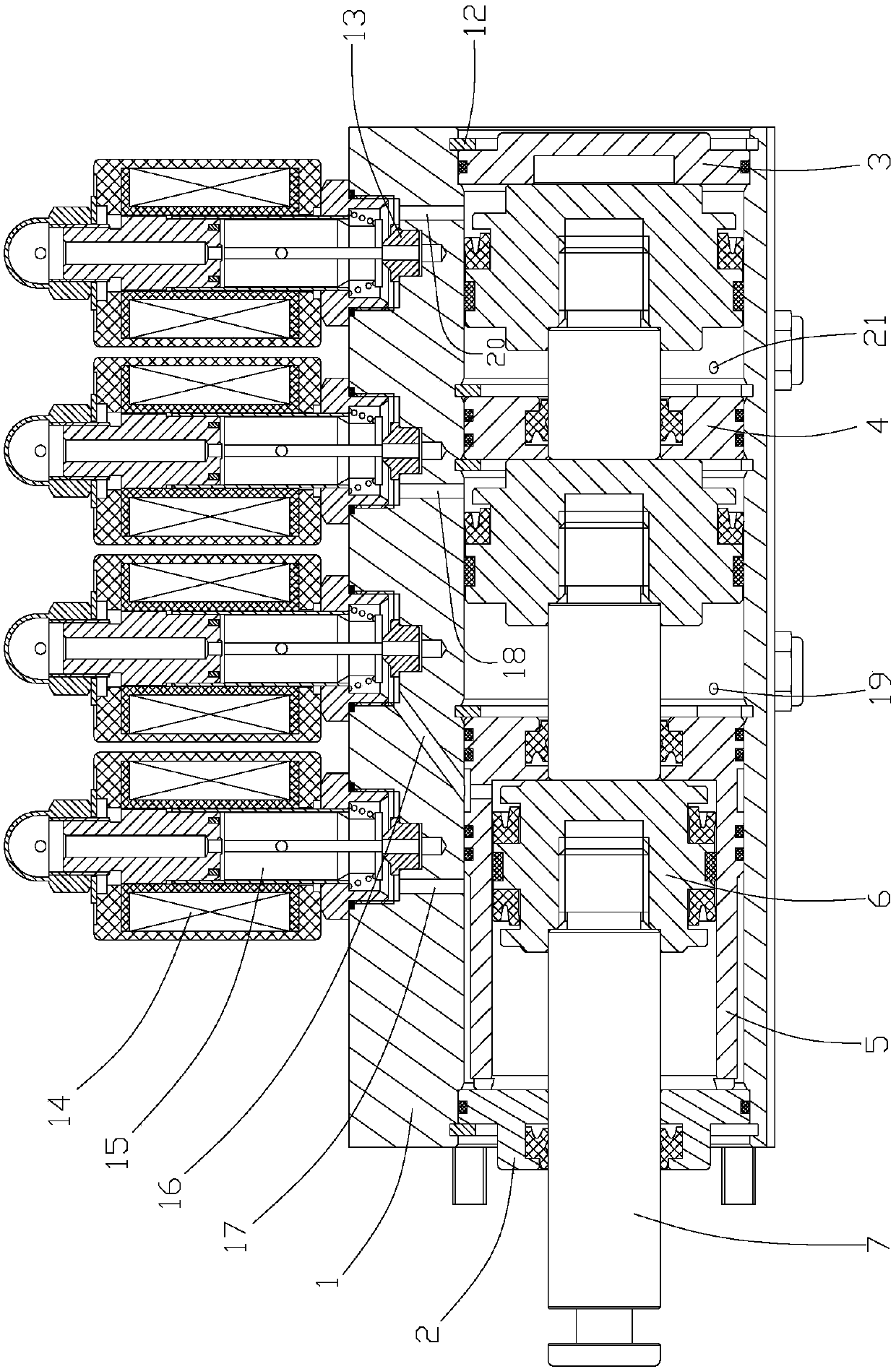
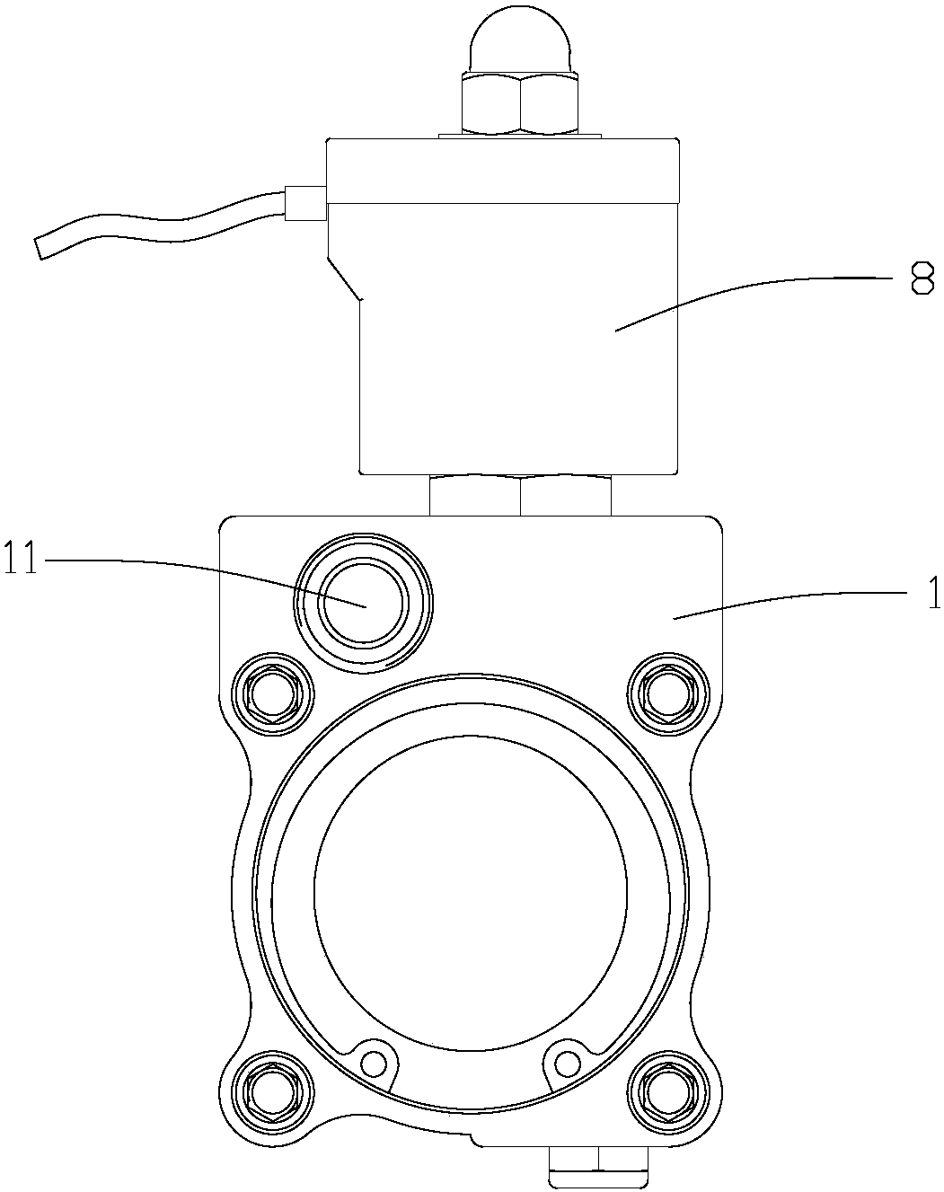
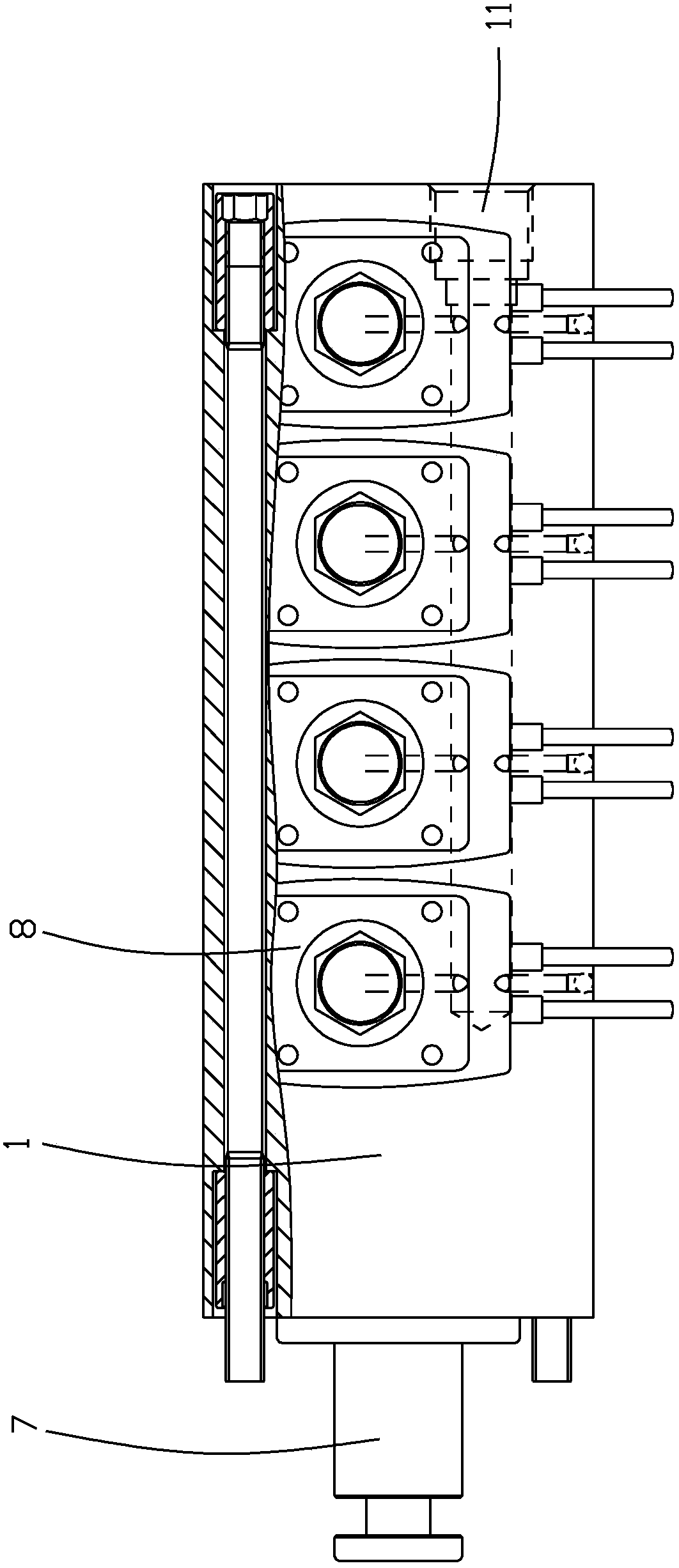
[0021] Implementation mode 1, see Figure 1-4 , a multi-stroke cylinder, including a cylinder 1, the cylinder 1 is provided with a tie rod according to the installation requirements, the two ends of the cylinder 1 are respectively provided with a front cover 2 and a rear cover 3, and the front cover 2 and the rear cover 3 pass through the holes respectively. The circlip 12 is fixed, and the cylinder 1 is provided with three piston chambers, which are respectively the first piston chamber, the second piston chamber and the third piston chamber, and the first piston chamber and the second piston chamber are separated by the cylinder liner 5, The function of the cylinder liner 5 is to change the diameter of the first piston chamber, thereby changing the thrust of the piston rod 7, the second piston chamber and the third piston chamber are separated by the middle cover 4, and the inner wall of the cylinder barrel 1 is provided with a number of annular slots, A circlip 12 for the h...

Embodiment approach 2

[0026] Implementation mode 2, see Figure 5 , the difference between this embodiment and Embodiment 1 is that: the first piston chamber, the second piston chamber and the third piston chamber are arranged in the cylinder barrel 1, and the first air inlet communicating with the first piston chamber is arranged on the cylinder barrel 1 The hole 16 and the first exhaust hole 17, the second air intake hole 18 and the second exhaust hole 19 communicating with the second piston chamber, and the third air intake hole 20 and the third exhaust hole corresponding to the third piston chamber 21. Six electromagnetic coil assemblies 8 are provided on the upper end of the cylinder 1, and the valve cavities of the six electromagnetic coil assemblies 8 are respectively connected with the first air inlet 16, the first air outlet 17, the second air inlet 18, the second air inlet The second exhaust hole 19 , the third air intake hole 20 and the third exhaust hole 21 communicate with each other. ...


PUM


Abstract

The invention discloses a multi-stroke cylinder. The multi-stroke cylinder comprises a cylinder barrel. A front cover and a rear cover are arranged at the two ends of the cylinder barrel correspondingly. At least two piston cavities are formed in the cylinder barrel. Every two adjacent piston cavities are partitioned through a middle cover or a cylinder sleeve. Each piston cavity is internally provided with a piston assembly. A gas inlet hole and an exhaust hole are formed in the position, corresponding to each piston cavity, on the cylinder barrel. Multiple electromagnetic coil assemblies are arranged on the cylinder barrel. Each electromagnetic coil assembly is provided with a valve cavity, a gas inlet and an exhaust port. A gas inlet passageway is further arranged on the cylinder barrel. The gas inlets of all the electromagnetic coil assemblies communicate with the gas inlet passageway. The valve cavities of all the electromagnetic coil assemblies communicate with the gas inlet holes or the exhaust holes in the cylinder barrel correspondingly. The multi-stroke cylinder is simple in structure, the requirements for the assembling and machining precision of parts are lower, cost can be effectively reduced, and a control system of the multi-stroke cylinder is simpler and more convenient.

Description

technical field [0001] The invention relates to the field of cylinders, in particular to an integrated multi-stroke cylinder. Background technique [0002] A multi-stroke cylinder refers to a cylinder in which the piston has multiple stroke control positions. The multi-stroke cylinder is often used to drive the actuator to form multiple position states. At present, the cylinder body of the multi-stroke cylinder adopts a segmented structure, that is, the multi-segment cylinder body is connected in series through a tie rod, and then the segmented piston is installed in the corresponding cylinder body. The exhaust hole is used to drive the piston in the cylinder, so that the outermost piston rod can obtain different stroke positions. For example, a kind of multi-stroke cylinder disclosed by patent notification number CN104564898A, its cylinder is made up of multiple layers, each layer has an independent cylinder, each cylinder has different strokes, and the piston rod of each ...

Claims


Application Information

Patent Timeline
Patent Type & Authority Patents(China)
IPC IPC(8): F15B15/14F15B15/20
CPCF15B15/1414F15B15/1428F15B15/1447F15B15/20F15B2211/70
Inventor 任建明王全民
Owner NINGBO QUANSHENG CENTURY PNEUMATIC TECH CO LTD
Learn More