
A corrugated fin heat exchange structure and design method for mine air cooler

A technology of corrugated fins and heat exchange structure, which is applied in the field of heat exchange, can solve the problems of large volume of heat exchange equipment, difficult to use, easy to accumulate dust and scale, etc., and achieve low investment cost, reasonable structure design, and simple processing and production Effect

Active Publication Date: 2018-04-20
XIAN UNIV OF SCI & TECH
View PDF8 Cites 0 Cited by
  • Summary
  • Abstract
  • Description
  • Claims
  • Application Information

AI Technical Summary

Problems solved by technology

Most of the heat exchange structures disclosed in the above invention patent application documents are arranged on the straight fins with delta-wing longitudinal vortex generators to enhance the heat exchange capacity. The channels formed by the straight fins themselves have little disturbance to the air and are prone to dust accumulation. scale, making the heat exchange equipment bulky, it is difficult to apply to the high temperature operation area of ​​the coal mine

Method used


Image

  • A corrugated fin heat exchange structure and design method for mine air cooler
  • A corrugated fin heat exchange structure and design method for mine air cooler
  • A corrugated fin heat exchange structure and design method for mine air cooler

Examples


Embodiment Construction

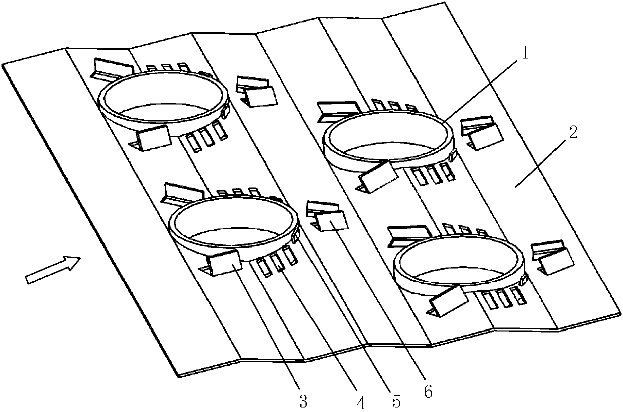
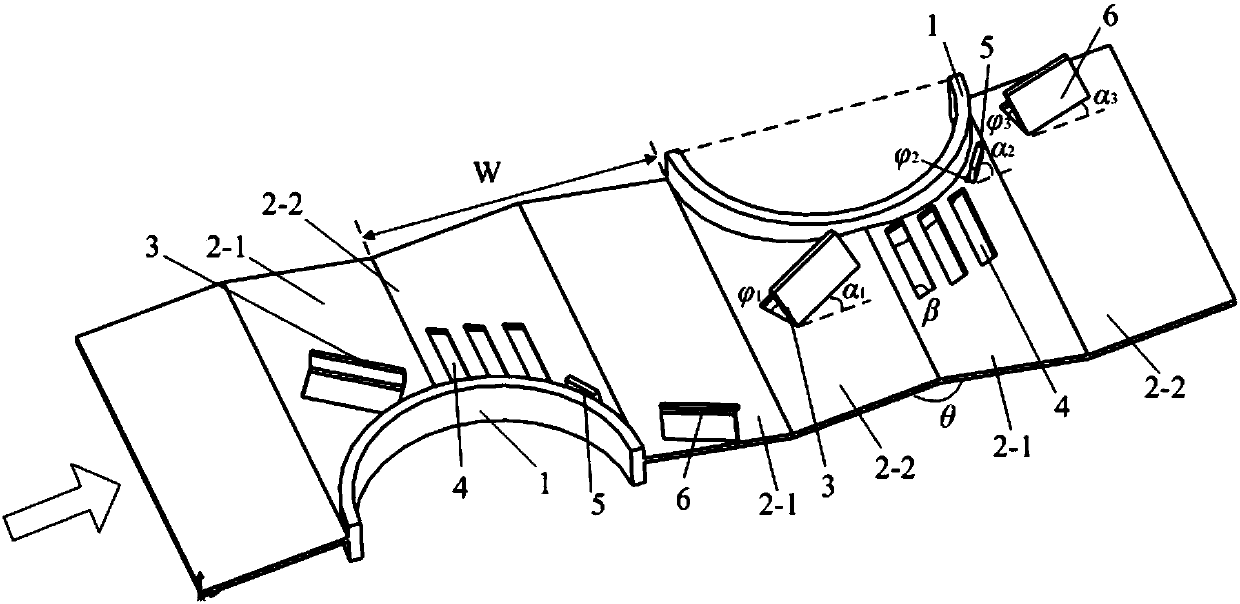
[0042] Such as figure 1 , figure 2 The shown corrugated fin heat exchange structure for the mine air cooler includes multiple rows of heat exchange tubes 1 and corrugated fins 2 installed on the multiple rows of heat exchange tubes 1, and the corrugated fins 2 are zigzag corrugated plates; Multiple rows of heat exchange tubes 1 are evenly arranged, and each row of heat exchange tubes 1 includes a plurality of heat exchange tubes 1 arranged from front to back along the length direction of the corrugated fins 2, and the plurality of heat exchange tubes 1 are all arranged on the same straight line, the structure and size of the plurality of heat exchange tubes 1 are the same and they are evenly arranged; the heat exchange tubes 1 in two adjacent rows of heat exchange tubes 1 are arranged in a staggered manner; The corrugated fins 2 are composed of a plurality of corrugated fin units arranged from back to front along the flow direction of the airflow. The structure and size of t...


PUM


Abstract

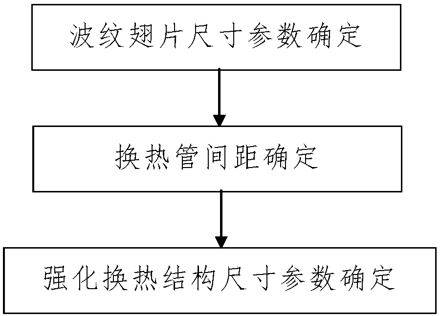
The invention discloses a corrugated fin heat exchange structure for a mine air cooler and a design method of the corrugated fin heat exchange structure. The corrugated fin heat exchange structure comprises multiple rows of heat exchange pipes and a corrugated fin. The corrugated fin is a sawtooth-shaped corrugated plate. The heat exchange pipes in the two rows of adjacent heat exchange pipes are staggered. The corrugated fin comprises a plurality of corrugated fin units. Each corrugated fin unit comprises two symmetric strip-shaped plates. A heat exchange pipe laying plate for allowing one row of heat exchange pipes to be laid is defined by three adjacent strip-shaped plates. Heat transfer enhancement structures are arranged on the outer sides of the heat exchange pipes. The design method comprises the following steps that first, the size parameters of the corrugated fin are determined; second, the distances between any two adjacent heat exchange pipes are determined; and third, the size parameters of the heat transfer enhancement structures are determined. The corrugated fin heat exchange structure is reasonable in design, simple and convenient to process and manufacture, and good in using effect. The heat exchange pipes are arranged on the corrugated fin, and the heat transfer enhancement structures are arranged on the outer sides of the heat exchange pipes, so that the heat exchange efficiency can be improved effectively, the size of the mine air cooler can be reduced, and installation and arrangement of high temperature borehole operation places are facilitated.

Description

technical field [0001] The invention belongs to the technical field of heat exchange, in particular to a corrugated fin heat exchange structure for a mine air cooler and a design method thereof. Background technique [0002] At present, with the increase of coal mining depth and the improvement of mechanization, high temperature heat damage in mine working face has become one of the bottlenecks restricting deep mining, and seriously affects the life safety and work efficiency of operators. Mine air-conditioning is the main means of treating and controlling high-temperature heat damage. As the terminal equipment, the air cooler is the most important heat exchange component in the mine cooling system. Its flow and heat transfer characteristics have an important impact on the operating efficiency and stability of the cooling system. . The widely used arrangement form of air cooler is the tube-fin type. Due to the limitation of the thermal properties of the air outside the tube...

Claims


Application Information

Patent Timeline
Patent Type & Authority Patents(China)
IPC IPC(8): F28F1/32
CPCF28F1/325
Inventor 张京兆
Owner XIAN UNIV OF SCI & TECH
Learn More