Calculation method for determining contribution of chemical flooding in enhancing recovery ratio

A calculation method and chemical flooding technology, which can be applied in the fields of calculation, fluid production, and earth-moving drilling, etc., and can solve the problems of different oil displacement efficiency, effective speed and effective period, etc.

Active Publication Date: 2016-10-26
CHINA NAT OFFSHORE OIL CORP +1
View PDF4 Cites 6 Cited by
  • Summary
  • Abstract
  • Description
  • Claims
  • Application Information

AI Technical Summary

Problems solved by technology

However, the author found an interesting phenomenon in the process of chemical flooding experiments for many years. If polymer solutions with different properties are used, not only the oil displacement efficiency is different, but also the

Method used


Image

  • Calculation method for determining contribution of chemical flooding in enhancing recovery ratio
  • Calculation method for determining contribution of chemical flooding in enhancing recovery ratio
  • Calculation method for determining contribution of chemical flooding in enhancing recovery ratio

Examples


Embodiment 1

[0030] Example 1. Calculation of the contribution of chemical flooding to enhanced oil recovery

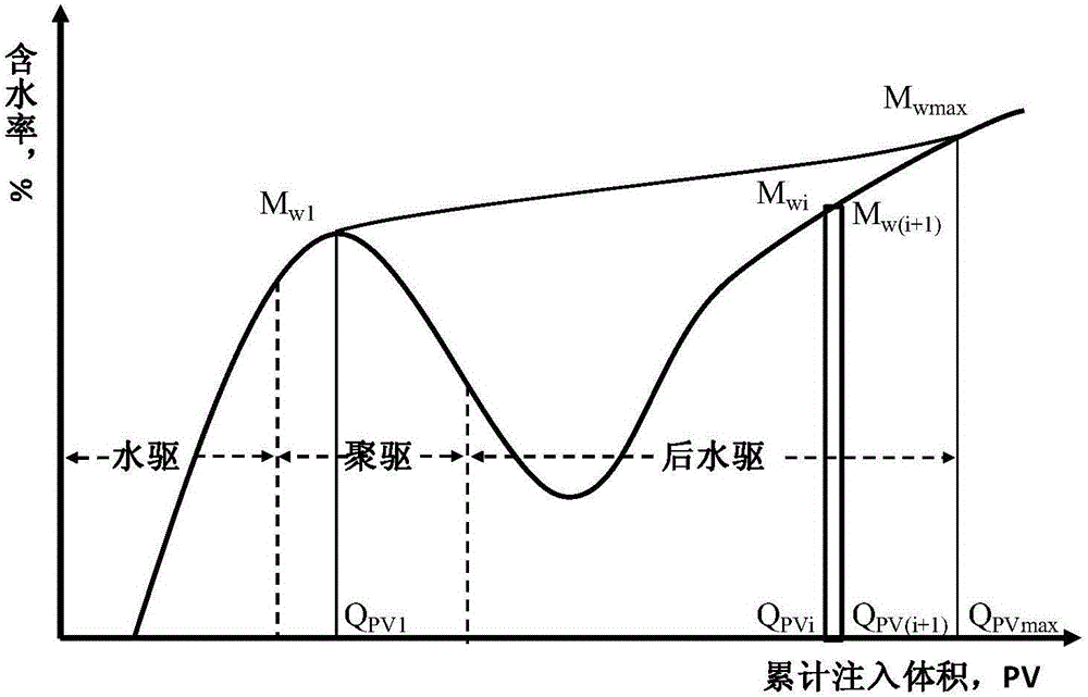
[0031] 1. Carry out chemical flooding experiments, take the cumulative injected PV volume of the flooding system as the abscissa, and take the water content of the produced fluid as the ordinate to make a chemical flooding water cut curve, as shown in figure 1 Shown, including water flooding stage, chemical flooding stage and post-water flooding stage water cut changes.

[0032] in such as figure 1 On the water cut curve shown, find the inflection point water cut M after the water flooding stage w1 , with M w1 As the starting point, the arc surface at the inflection point is tangent to the smooth upward extension to the tangent to the water content curve in the post-water flooding stage, and the tangent point is the water content M wmax ;

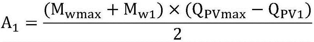
[0033] 2. Take the above two tangent points M w1 and M wmax As the starting point, draw a vertical line on the abscissa, and the interse...

Embodiment 2

[0041] Embodiment 2, polymer solution flooding performance research

[0042] (1) Oil displacement system for experiment: A hydrophobic association polymer oil displacement system with a viscosity of 25mpa.s was selected for the experiment.

[0043] (2) Experimental model and experimental conditions: three-layer equal-thickness heterogeneous cemented quartz sand model (4.5×4.5×30cm) for oil displacement test: permeability 2000mD, porosity 30%, temperature 65°C, water salinity 9374mg / L, polymer concentration 1750mg / L;

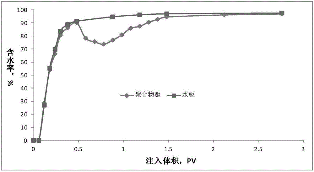
[0044] (3) The water cut curve obtained from the oil displacement experiment of the above oil displacement system (the cumulative injected PV volume of the oil displacement system is the abscissa, and the water content of the produced fluid is the ordinate) as follows: figure 2 shown;

[0045] (4) according to the method provided in embodiment 1, find the inflection point of the polymer flooding water cut curve to each water content data point of the tangent ...


PUM


Abstract

The invention discloses a calculation method for determining contribution of chemical flooding in enhancing a recovery ratio. The calculation method comprises the steps of: (1) taking an inflection point on a chemical flooding water content curve when a water content decreases after a water flooding phase as a starting point, and making an arc surface wherein the starting point locates tangent with the water content curve which smoothly extends upwards to a post-water-flooding phase, so as to obtain a straight line and a tangent point; (2) projecting the starting point and the tangent point to the horizontal axis to obtain two perpendicular lines; calculating an area of a closed region enclosed by the perpendicular lines, the straight line and the horizontal axis, wherein the area is denoted as A1; (3) dividing the closed region into an upper region and a lower region by the water content curve, and calculating an area of the lower region, wherein the area is denoted as A2; (4) and subtracting A2 from A1 to obtain delta A, wherein the delta A indicates the recovery ratio enhanced by chemical flooding. The calculation method is conductive to studying the relation between the reduced area size of the chemical flooding water content curve and oil displacement efficiency through the reduced area obtained by calculation.

Description

technical field [0001] The invention relates to a calculation method for determining the contribution of chemical flooding to enhanced recovery. Background technique [0002] Displacement experiment is the most commonly used method to evaluate the oil displacement effect of chemical oil displacement agents, and its oil displacement efficiency is one of the most concerned experimental results. However, the author found an interesting phenomenon in the process of chemical flooding experiments for many years. If polymer solutions with different properties are used, not only the oil displacement efficiency is different, but also the shape and area of ​​the water cut reduction curve of the produced fluid are also different, and this This situation may be related to a certain extent with the effective speed, effective period and effect limit of polymer flooding in the future. Considering that the size of the reduced area of ​​the chemical flooding water cut curve is related to th...

Claims


Application Information

Patent Timeline
IPC IPC(8): G06Q50/02E21B43/22
CPCE21B43/16G06Q50/02Y02A10/40
Inventor 张凤久
Owner CHINA NAT OFFSHORE OIL CORP
Why Eureka
Try Eureka