Module system for integrated antenna

An antenna and module technology, applied in the direction of antenna support/installation device, etc., can solve the problem of poor antenna efficiency and achieve the effect of performance improvement

Active Publication Date: 2016-10-26
CHANGSHU HONGBO COMM TECH CO LTD
View PDF15 Cites 3 Cited by
  • Summary
  • Abstract
  • Description
  • Claims
  • Application Information

AI Technical Summary

Problems solved by technology

This kind of setting method also makes the antenna suffer from more noise interference, and the antenna performance is also poor. It is also necessary to consider the electromagnetic radiation absorption rate (SAR) of safety regulations.

Method used


Image

  • Module system for integrated antenna
  • Module system for integrated antenna
  • Module system for integrated antenna

Examples


Embodiment Construction

[0037] In order to enable a further understanding of the features and technical content of the present invention, please refer to the following detailed description and accompanying drawings of the present invention, but these descriptions and accompanying drawings are only used to illustrate the present invention, and do not imply any limitation to the present invention. without any limitation on the scope of rights.

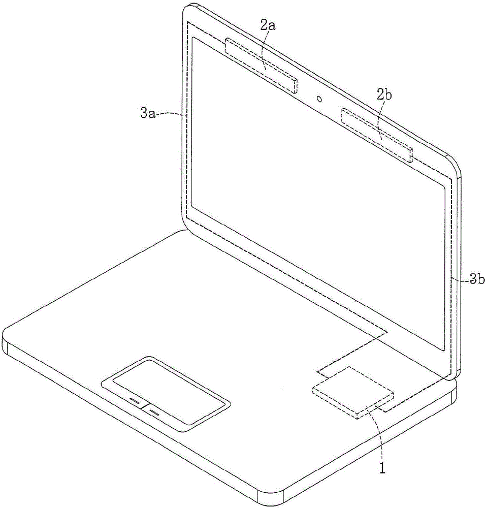
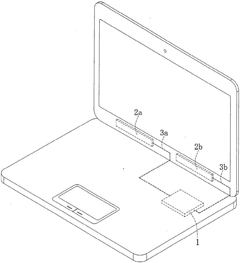
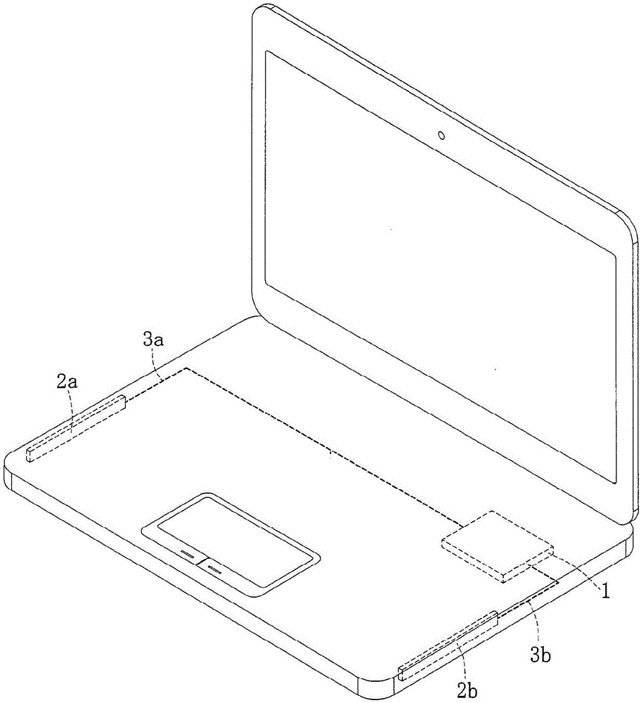
[0038] Please also see Figure 5A and Figure 5B , Figure 5A It is a schematic diagram of the position of the integrated antenna module system provided by the example of the present invention set on the screen (that is, "screen", the same below), Figure 5B It is a schematic diagram of the module system integrating antenna provided by the example of the present invention. Such as Figure 5A As shown, the integrated antenna module system 6 of this embodiment is used to be arranged adjacent to the upper side of the notebook computer, but the present inventio...


PUM


Abstract

The invention provides a module system for integrated antenna, which is used to be set in an electronic device with a display screen. The system includes a circuit board with at least one antenna excitation unit for coupling an antenna, a module grounding plane arranged on the circuit board, a wireless module arranged on the circuit board and electrically connected with the grounding module and the antenna excitation unit(s), a system grounding plane, a grounding metal electrically connected with the grounding module and the grounding system, a lens module arranged on the circuit board and electrically connected with the grounding module, and a digital signal line electrically connected with the wireless module and the lens module to serve as digital transmission medium for the wireless module and the lens module. The wireless module, the lens module and the circuit board form an integrated module, which is arranged at the upper side of a display screen close to an electronic device. As the antenna is a hidden one formed by the integration of a lens module, the problem of the winding of coaxial cables and the radio frequency signal loss of coaxial cables can be solved, thus improving the performances of the antenna.

Description

technical field [0001] The invention belongs to the technical field of antennas for electronic devices, and in particular relates to a module system for integrating antennas. Background technique [0002] The electronic devices mentioned above mainly refer to, but are not absolutely limited to, notebook computers. Figure 1 to Figure 4 is a schematic diagram of a hidden antenna of an electronic device such as a notebook computer in the prior art. Specifically, the following design situations are respectively shown according to the installation positions of the antennas: [0003] exist figure 1 In the design of the present invention, one or more than two antennas 2a, 2b can be arranged on the upper side of the screen of the notebook computer, so that a better radiation pattern can be achieved, and the environment near the antennas is relatively simple and suffers less noise interference. The antenna 2a and the antenna 2b are respectively connected to the wireless module 1 ...

Claims


Application Information

Patent Timeline
Patent Type & Authority Applications(China)
IPC IPC(8): H01Q1/22
CPCH01Q1/22
Inventor 邱宗文颜红方张耀元施佑霖魏嘉贤李冠纬李荣耀
Owner CHANGSHU HONGBO COMM TECH CO LTD
Why Eureka
Try Eureka