High gain T-shaped probe feed millimeter wave patch antenna
A high-gain, wave patch technology, applied in the field of millimeter-wave patch antennas and millimeter-wave patch antennas fed by T-shaped probes, can solve the problems of high free space transmission attenuation, strong gas absorption effect, etc., and achieve good Radiation characteristics, low cross-polarization, effect of pattern stabilization
- Summary
- Abstract
- Description
- Claims
- Application Information
AI Technical Summary
Problems solved by technology
Method used
Image
Examples
Embodiment 1
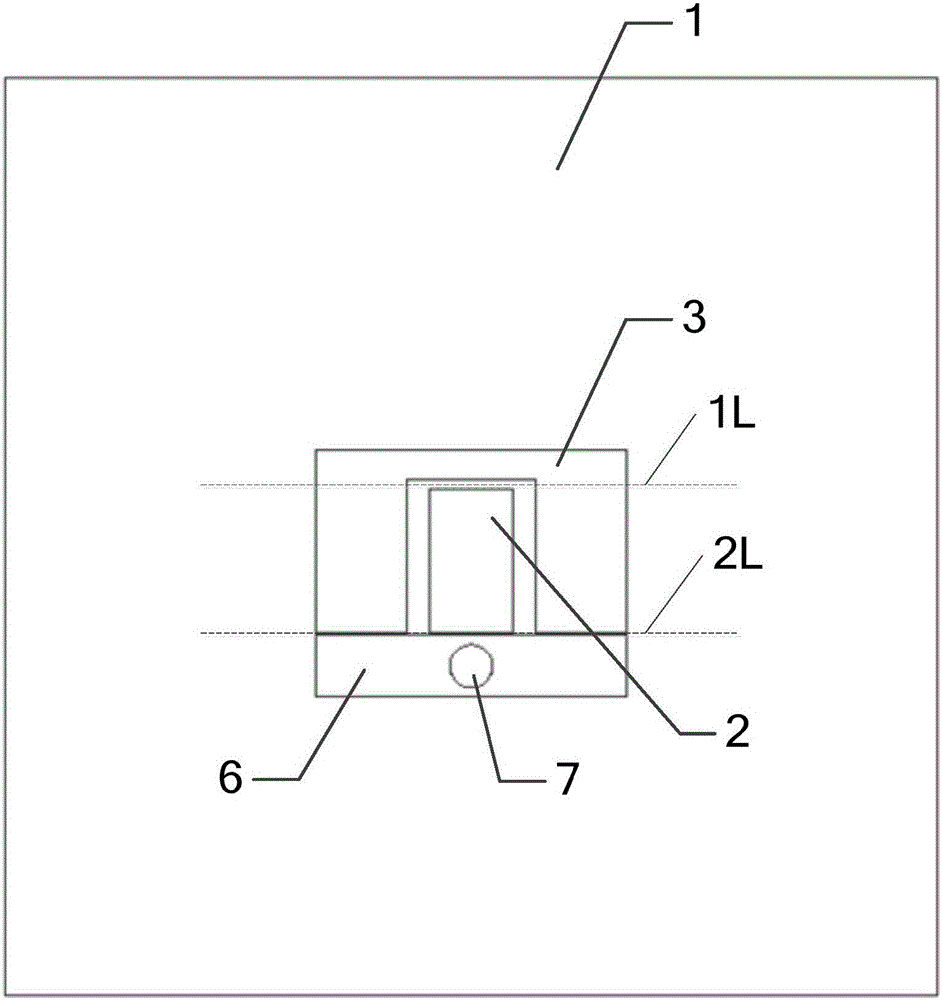
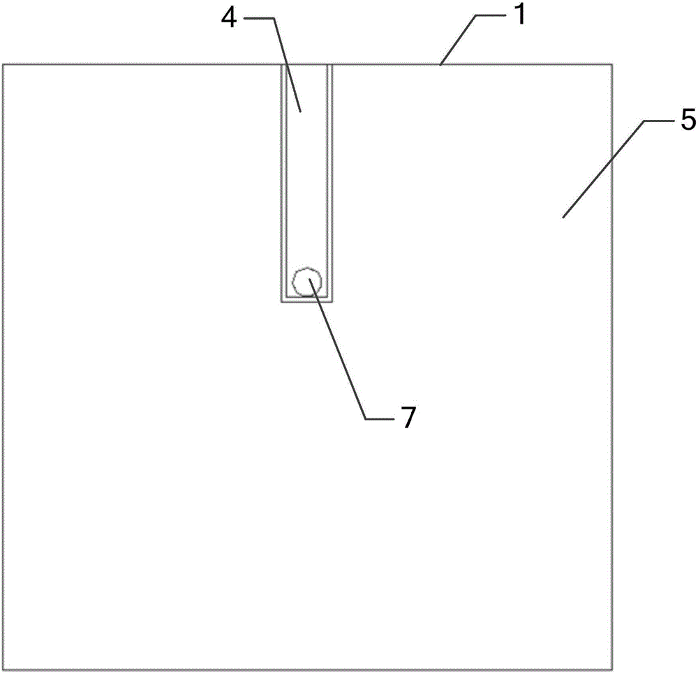
[0031] Such as figure 1 and figure 2 As shown, the millimeter-wave patch antenna of this embodiment includes a first dielectric substrate 1, on which a T-shaped probe, a first radiation patch 2, a second radiation patch 3, a first The coplanar waveguide transmission line 4 and the second coplanar waveguide transmission line 5 .
[0032] The millimeter-wave patch antenna of this embodiment uses a T-shaped probe to feed the first radiating patch 2 and the second radiating patch 3 to generate two resonant modes, in which the first radiating patch 2 generates High-frequency resonance mode, the second radiation patch 3 produces a low-frequency resonance mode, which ensures that the antenna has a wider impedance bandwidth; the T-shaped probe is composed of a horizontal patch 6 and a vertical metal via 7, so The horizontal patch 6, the first radiating patch 2 and the second radiating patch 3 are arranged on the front of the first dielectric substrate 1, and between the horizontal ...
Embodiment 2
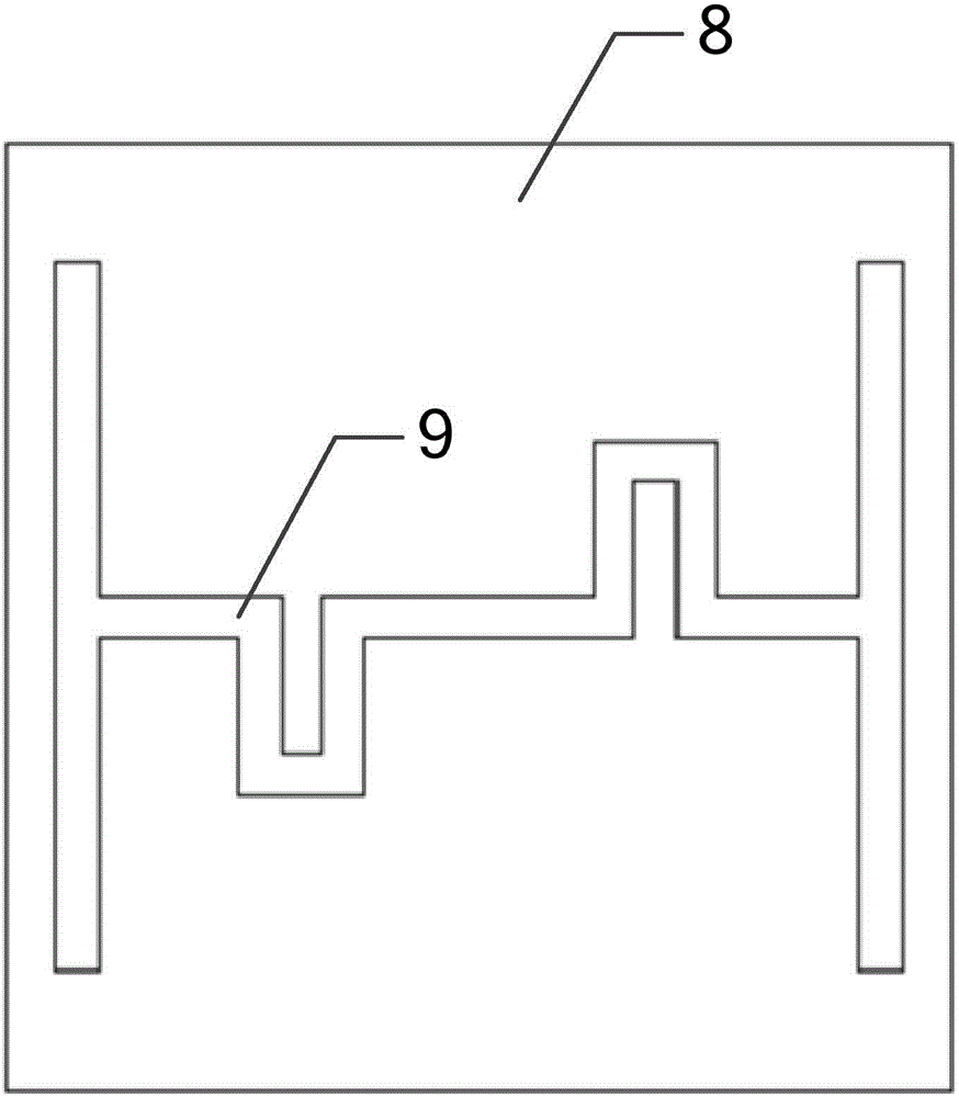
[0035] Such as Figure 1 to Figure 4 As shown, the millimeter-wave patch antenna of this embodiment also includes two second dielectric substrates 8, the two second dielectric substrates 8 are symmetrical up and down, and each second dielectric substrate 8 is arranged on the first dielectric substrate 1 The upper end, and one or more ZIM units 9 are loaded on the front side of each second dielectric substrate 8. The following describes the loading of one ZIM unit 9 and three ZIM units 9 on the second dielectric substrate 8:
[0036] 1) When a ZIM unit 9 is loaded on the front of each second dielectric substrate 8, such as image 3 As shown, the ZIM unit 9 includes a first vertical section, a second vertical section and a bent section, the first vertical section and the second vertical section are left and right symmetrical, and the two ends of the bent section are respectively Connected with the first vertical section and the second vertical section, the bent section consists...
Embodiment 3
[0041] In the millimeter-wave patch antenna of this embodiment, the dielectric constant of the first dielectric substrate 1 is 2.2, and the dielectric constant of the two second dielectric substrates 2 is 5.9. The entire millimeter-wave patch antenna uses a T-shaped probe to The radiating patch (the second radiating patch 3) and the small radiating patch (the first radiating patch 2) are fed to enable the antenna to achieve a wide impedance bandwidth. The T-shaped probe consists of a horizontal patch 6 and a vertical metal The horizontal patch 6 is a rectangular copper sheet, the center of the vertical metal via hole 7 is located at the geometric center of the rectangular copper sheet, and the horizontal patch 6, the first radiation patch 2 and the second radiation patch 3 is printed on the front of the first dielectric substrate 1; the entire millimeter-wave patch antenna is fed through the coplanar waveguide, and the first coplanar waveguide transmission line 4 and the second...
PUM
 Abstract
Description
Claims
Application Information
 - R&D
- Intellectual Property
- Life Sciences
- Materials
- Tech Scout
- Unparalleled Data Quality
- Higher Quality Content
- 60% Fewer Hallucinations
Browse by: Latest US Patents, China's latest patents, Technical Efficacy Thesaurus, Application Domain, Technology Topic, Popular Technical Reports.
© 2025 PatSnap. All rights reserved.Legal|Privacy policy|Modern Slavery Act Transparency Statement|Sitemap|About US| Contact US: help@patsnap.com


