llc resonant converter circuit

A resonant converter and circuit technology, which is applied in the direction of instruments, DC power input conversion to DC power output, electrical components, etc., to achieve the effects of reducing output ripple, solving power consumption increase, and low cost

Active Publication Date: 2018-06-29
TAIHUA WISDOM IND GRP CO LTD
View PDF3 Cites 0 Cited by
  • Summary
  • Abstract
  • Description
  • Claims
  • Application Information

AI Technical Summary

Problems solved by technology

[0008] In view of this, the technical problem to be solved in this application is to provide an LLC resonant converter circuit, which can control the output at no-load, the circuit is simple and practical, and can realize extremely low no-load power without significantly increasing the cost. consumption

Method used


Image

  • llc resonant converter circuit
  • llc resonant converter circuit
  • llc resonant converter circuit

Examples


Embodiment 1

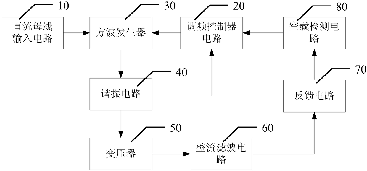
[0061] see figure 1 Shown is a structural block diagram of an LLC resonant converter circuit described in this application. In the figure, the LLC resonant converter circuit includes: DC bus input circuit 10, frequency modulation controller circuit 20, square wave generator 30, resonant circuit 40, transformer 50, rectification and filtering circuit 60, feedback circuit 70 and no-load detection circuit 80,

[0062] The DC bus input circuit 10 is connected to the square wave generator 30 for inputting a stable DC voltage to the entire LLC resonant converter circuit;

[0063] The frequency modulation controller circuit 20 is connected to the input terminal of the square wave generator 30, and connected to the RC oscillator circuit inside the feedback circuit, for generating a pair of Complementary driving signals with a fixed duty cycle of 50% and adjustable frequency;

[0064] The square wave generator 30 is a full-bridge or half-bridge drive circuit composed of MOSFET switc...

Embodiment 2

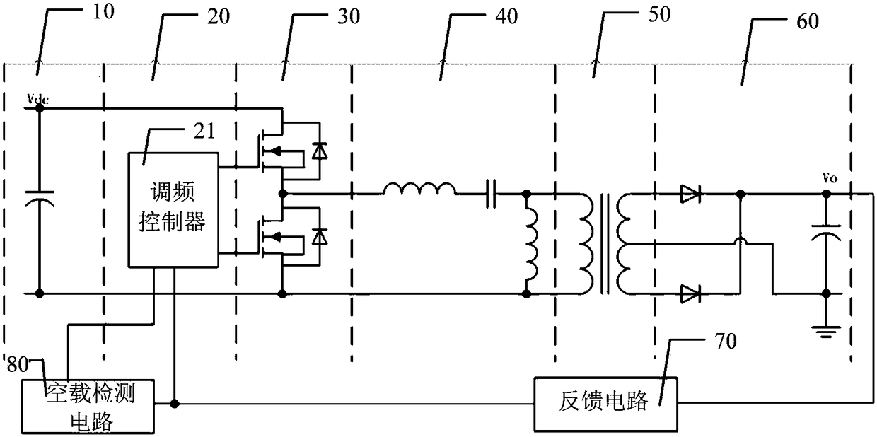
[0072] see figure 2 Shown is a schematic structural diagram of the LLC resonant converter circuit of the present application. In this figure, the configuration of the DC bus input circuit 10, the square wave generator 30, the resonant circuit 40, the transformer 50, and the rectification and filtering circuit 60, as well as the connection relationship between these circuits, the feedback circuit and the no-load detection circuit 80 are shown in detail.

[0073] The DC bus input circuit 10 inputs a stable DC voltage of about 400V generated by the PFC circuit to the entire LLC resonant converter circuit.

[0074] The FM controller 21 is externally connected to an RC oscillating circuit. By changing the parameter of the resistor R in the RC oscillating circuit, the RC oscillating frequency is changed, thereby outputting a pair of driving signals whose duty cycle is fixed at 50%, complementary, and whose frequency is variable, and drives the The signal is input to the input term...

Embodiment 3

[0102] Application examples of the LLC resonant converter circuit of the present invention are provided below.

[0103] Such as figure 2 Shown is the schematic diagram of the LLC resonant converter circuit of the present invention, including: a DC bus input circuit 10, a frequency modulation controller circuit 20, a square wave generator 30, a resonant circuit 40, a transformer 50, a rectifying and filtering circuit 60, a feedback circuit 70 and No-load detection circuit 80.

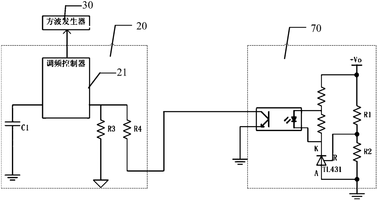
[0104] The following combination image 3 and Figure 4 The control process of the LLC resonant converter circuit of the present invention is described.

[0105] Such as image 3 As shown, the capacitor C1, the resistor R3, the resistor R4 in the frequency modulation controller circuit 20, and the RC oscillation circuit composed of the optocoupler in the feedback circuit 70 determine the output frequency of the frequency modulation controller 21, wherein the R parameter is composed of R4 and The op...


PUM


Abstract

The invention discloses an LLC resonance converter circuit, which comprises a DC bus input circuit, a frequency modulation controller circuit, a square wave generator, a resonance circuit, a transformer, a rectifier and filter circuit, a feedback circuit and a no-load detection circuit, wherein the no-load detection circuit is connected to the feedback circuit and the frequency modulation controller circuit and is used for lastingly detecting feedback signal voltage in the feedback circuit, comparing the feedback signal voltage with reference voltage, controlling a frequency modulation controller in the frequency modulation controller circuit to enter a standby state when the feedback signal voltage is lower than the reference voltage and stopping outputting a drive signal, so that the square wave generator stops outputting a square wave. According to the LLC resonance converter circuit, controllable output in a no-load state is achieved; the circuit is simple and practical; and extremely low no-load power consumption can be achieved under the condition of not significantly increasing the cost.

Description

technical field [0001] The present application relates to the technical field of switching power supplies, in particular to an LLC resonant converter circuit including a no-load detection circuit. Background technique [0002] With the continuous development of switching power supply technology, the operating frequency of switching power supply is getting higher and higher, which greatly reduces the size of passive components such as transformers, inductors and filters, and makes the power density of power supply higher and higher. At higher frequencies, switching losses become the main limitation in power supply design. In order to reduce the switching loss and allow the power supply to operate at high frequency, the resonant switching technology is developed. The resonant switching technology converts the current flowing through the switching tube into a sine wave from a square wave, so that the switching device operates at zero voltage (ZVS) or zero current ( ZCS) condit...

Claims


Application Information

Patent Timeline
Patent Type & Authority Patents(China)
IPC IPC(8): H02M3/338
CPCH02M3/3381H02M3/3385Y02B70/10
Inventor 郝敬全赵吉祥徐文鹏王淑平马述杰居昌桥李亮报徐成龙吕绍平
Owner TAIHUA WISDOM IND GRP CO LTD
Why Eureka
Try Eureka