Induction cooker air channel structure and induction cooker

An induction cooker and air duct technology, which is applied to the structural parts of electrical equipment, electrical components, household stoves/stoves, etc. Simple, solve the effect of unsatisfactory cooling effect

Active Publication Date: 2016-10-26
GREE ELECTRIC APPLIANCES INC
View PDF3 Cites 0 Cited by
  • Summary
  • Abstract
  • Description
  • Claims
  • Application Information

AI Technical Summary

Problems solved by technology

[0004] The invention provides an induction cooker air duct structure and an induction cooker to solve the problem in the prior art that the temperature rise of mainboard components affects the life of the whole machine

Method used


Image

  • Induction cooker air channel structure and induction cooker
  • Induction cooker air channel structure and induction cooker
  • Induction cooker air channel structure and induction cooker

Examples


Embodiment Construction

[0026] The embodiments of the present invention will be described in detail below with reference to the accompanying drawings, but the present invention can be implemented in many different ways defined and covered by the claims.

[0027] The invention provides an induction cooker air channel structure, which is especially suitable for use in an ultra-thin induction cooker, which can not only achieve the purpose of energy saving, but also greatly reduce the problem of temperature rise of electronic components on the main board.

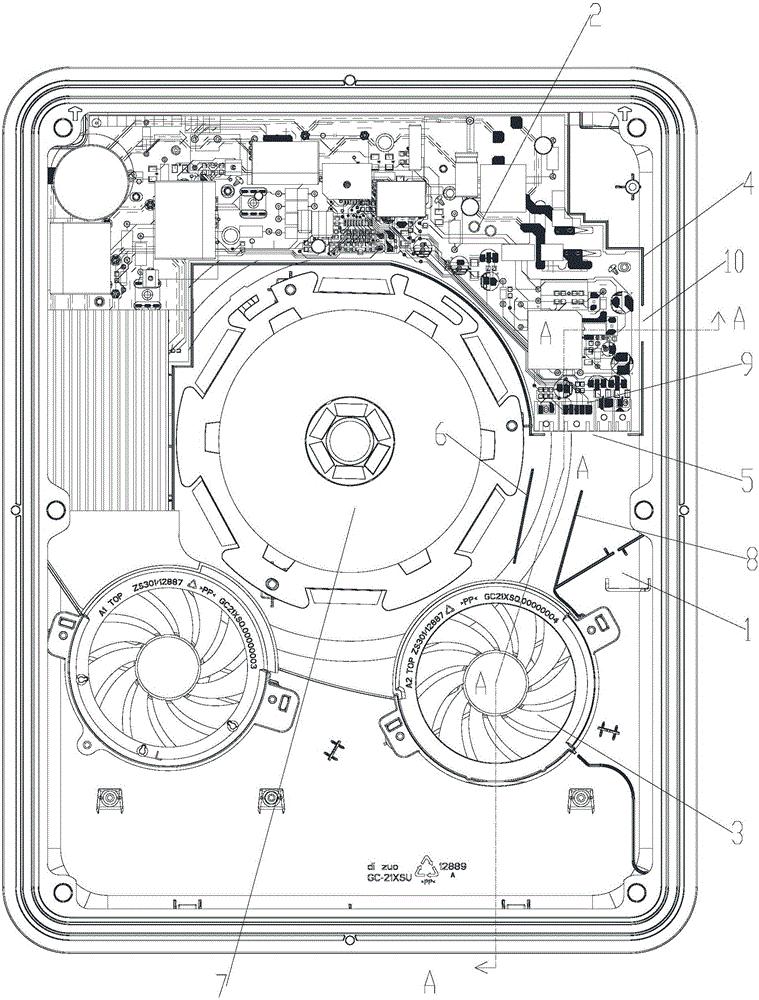
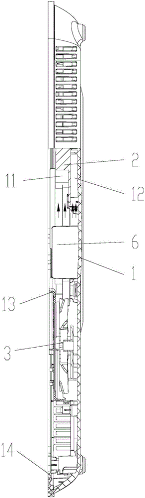
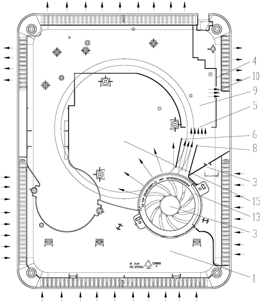
[0028] Please refer to Figure 1 to Figure 8 , the main board 2 is installed on the base 1, in order to realize the heat dissipation and cooling of the upper layer 11 and the lower layer 12 of the main board 2, a fan 3 is arranged on the outside of the main board 2, wherein, the gap between the main board 2 and the base 1 is provided with a surrounding The ribs 4 and surrounding ribs 4 are arranged around the circumference of the main board 2 . Where...


PUM


Abstract

The invention provides an induction cooker air channel structure and an induction cooker. The induction cooker air channel structure comprises a foundation, a main board mounted on the foundation, a blower fan arranged at an outer side of the main board, and surrounding ribs circumferentially arranged around the main board, wherein the surrounding ribs are provided with air inlets used for leading outgoing air of the blower fan into a gap between the main board and the foundation. The induction cooker air channel structure is advantaged in that the air of the blower fan can be led by the air inlets on the surrounding ribs to simultaneously flow through an upper layer and a lower layer of the main board, a problem of non-ideal integral radiation effect of a super-thin induction cooker can be greatly solved, especially temperature rising of components of the main board can be reduced, uniform radiation of each component of the main board can be realized, so integral service life of the super-thin induction cooker can be prolonged, the structure is simple, cost is low, and radiation effects are good.

Description

technical field [0001] The invention relates to the field of household appliances, in particular to the field of induction cookers, in particular to an induction cooker air duct structure and an induction cooker. Background technique [0002] The induction cooker mainly uses the alternating magnetic field generated by the electromagnetic coil for heating. In order to generate an alternating magnetic field, a high-frequency alternating current needs to be passed into the electromagnetic coil, which requires switching elements such as IGBTs to control the current flowing into the electromagnetic coil. In this way, components such as IGBT and electromagnetic coil will generate high heat, so it is necessary to design a corresponding heat dissipation structure on the induction cooker. [0003] At present, the mainstream ultra-thin induction cooker on the market, due to the thinner thickness, the air inlet and outlet space becomes smaller, and the ultra-thin induction cooker uses...

Claims


Application Information

Patent Timeline
Patent Type & Authority Applications(China)
IPC IPC(8): H05B6/42F24C7/00H05K7/20
CPCH05B6/42H05K7/20136F24C7/002
Inventor 潘海元刘博吴志勇曹林劳承云罗汉兵侯雪丹朱露露张帅卢耀臻陈伟
Owner GREE ELECTRIC APPLIANCES INC
Why Eureka
Try Eureka