Aerosol phase function observing system and observing method thereof

An observation system and aerosol technology, applied in the field of atmospheric detection, to achieve the effect of simple, effective and low-cost observation system

Active Publication Date: 2016-11-02
PEKING UNIV
View PDF5 Cites 5 Cited by
  • Summary
  • Abstract
  • Description
  • Claims
  • Application Information

AI Technical Summary

Problems solved by technology

Some of these researches on the phase function of aerosols are carried out on aerosol particles in the laboratory, and some are used to observe cloud droplets and i

Method used


Image

  • Aerosol phase function observing system and observing method thereof
  • Aerosol phase function observing system and observing method thereof
  • Aerosol phase function observing system and observing method thereof

Examples


Embodiment Construction

[0041] The present invention will be further elaborated below through specific embodiments in conjunction with the accompanying drawings.

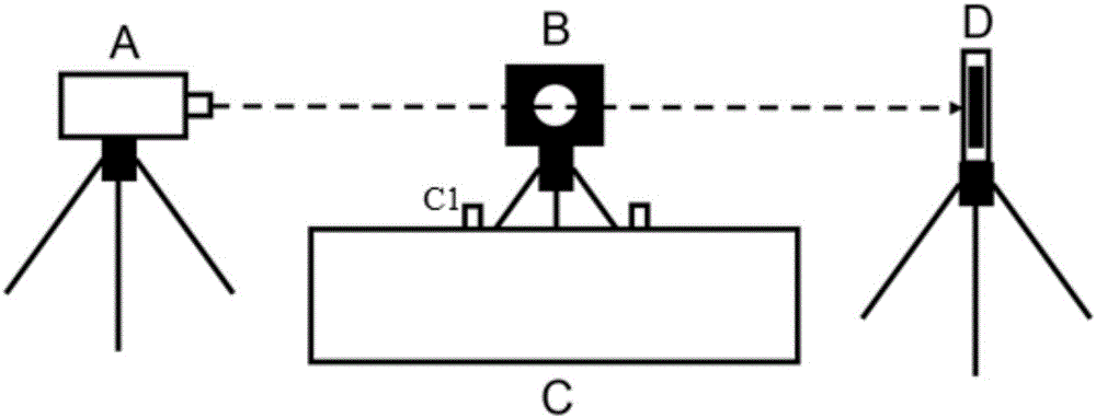
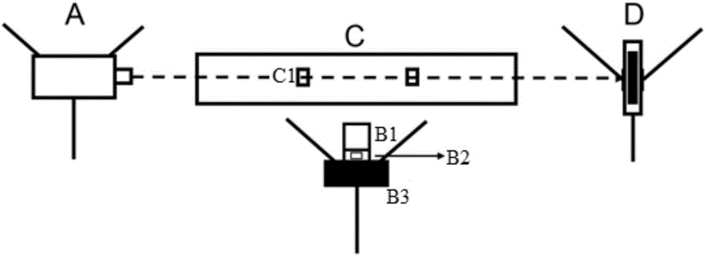
[0042] like figure 1 and figure 2 As shown, the aerosol phase function observation system of the present embodiment includes: a laser emitting unit A, an optical trap D, a turbidity meter C, a scattering signal receiver B and a computer; wherein the laser emitting unit A emits a continuous laser in the horizontal direction, An optical trap D is installed at the end of the laser beam to absorb the remaining laser light; a turbidity meter C is installed below the laser beam, and the air inlet C1 of the turbidity meter is aligned with the laser beam, and the backscattering coefficient of the aerosol hemisphere is measured; Next to the laser beam and at the same position as the laser beam, the scattered signal receiver B is installed; the scattered signal receiver B includes a wide-angle lens B1, a laser filter B2 and a CCD camera B3, and th...


PUM


Abstract

The invention discloses an aerosol phase function observing system and an observing method thereof. The aerosol phase function observing system comprises a laser emission unit, a light trap, a turbidimeter, a scattered signal receiver and a computer. The turbidimeter is installed below a laser beam, and aerosol hemisphere backscattering coefficient is obtained through measurement. The scattered signal receiver is installed beside the laser beam and at the same height of the laser beam. By combining a signal obtained by a CCD camera and the aerosol hemisphere backscattering coefficient measured by the turbidimeter, aerosol phase function is obtained. Different angles of scattering information can be obtained at the same time, and the influence of aerosol scattering performance changing with time on results is avoided. The observing system is simple and effective, is low-cost, provides a new technical means for observation of aerosol phase function, and provides supports for remote sensing observations of inversion of aerosol optical properties related instruments.

Description

technical field [0001] The invention relates to atmospheric detection technology, in particular to an aerosol phase function observation system and an observation method thereof. Background technique [0002] Aerosols are tiny particles suspended in the air, often referred to simply as atmospheric particulate matter. When radiation is transmitted in the atmosphere, it is scattered by different components such as gases and aerosols in the atmosphere, and its intensity, transmission direction, and polarization state will all change. In most cases, since solar radiation is natural light, the scattered light in the atmosphere is distributed axisymmetrically. Therefore, this distribution can be described by a single plane angle, 0 degrees means that the scattered light is forward scattered in the same direction as the incident light, 180 degrees means that the scattered light is back scattered in the opposite direction to the incident light, and the distance between the scattere...

Claims


Application Information

Patent Timeline
IPC IPC(8): G01N21/49
CPCG01N21/49G01N2201/06113
Inventor 赵春生边宇轩赵罡旷烨陶江川
Owner PEKING UNIV
Why Eureka
Try Eureka