DMD (digital micromirror device)-based four-dimensional laser radar imaging device and method

A lidar imaging, four-dimensional technology, applied in the direction of measurement device, electromagnetic wave re-radiation, utilization of re-radiation, etc. problems, to enhance the ability to deal with complex battlefield environments, strong anti-interference, and high image resolution.

Active Publication Date: 2016-11-02
XIAN SHENQIONG PHOTOELECTRIC TECH CO LTD
View PDF6 Cites 6 Cited by
  • Summary
  • Abstract
  • Description
  • Claims
  • Application Information

AI Technical Summary

Problems solved by technology

This solution has the advantages of simple structure and fast imaging speed. However, the core device in the non-scanning laser active imaging system is the APD array detector, which is very expensive. Taking the Si type 32×32APD array as an example, each It costs about 100,000 yuan. If it is replaced with a military-grade InGaAs APD array detector with higher sensitivity, the price of a single one will be close to one million. The high price seriously restricts the research and application of non-scanning laser active imaging technology. ; In addition, due to the constraints of the manufacturing process and cost, the resolution of the APD array is relatively low, generally around 32×32, and it is difficult to obtain a clear target image

Method used


Image

  • DMD (digital micromirror device)-based four-dimensional laser radar imaging device and method
  • DMD (digital micromirror device)-based four-dimensional laser radar imaging device and method
  • DMD (digital micromirror device)-based four-dimensional laser radar imaging device and method

Examples


Embodiment Construction

[0041] The present invention will be further described in detail below in conjunction with the accompanying drawings and specific embodiments.

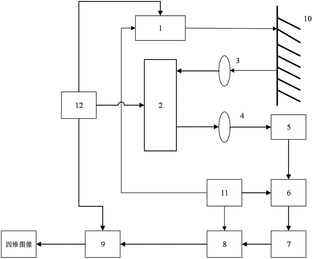
[0042] Such as figure 1 As shown, the DMD-based four-dimensional lidar imaging device of the present invention includes a launcher 1, a target 10 fixed at the light output end of the launcher 1, a first convergent lens 3 fixed on the reflected light path of the target 10, and a first convergent lens 3 fixed on The digital micromirror device DMD2 on the converging optical path is fixed on the second converging lens 4 on the reflection optical path of the digital micromirror device DMD2, and is fixed on the receiving device 5 on the converging optical path of the second converging lens 4; the frequency mixing device connected with the receiving device 5 device 6, an intermediate frequency amplifier 7 connected to the mixer 6, a quadrature phase detector 8 connected to the intermediate frequency amplifier 7, and a signal processing devic...


PUM


Abstract

The invention relates to a DMD (digital micromirror device)-based four-dimensional laser radar imaging device and a DMD (digital micromirror device)-based four-dimensional laser radar imaging method. The device comprises a transmitting device, a target fixed at the light outgoing end of the transmitting device, a first converging lens fixed on the reflected light path of the target, a digital micromirror device (DMD) fixed on the convergent light path of the first converging lens, a second converging lens fixed on the reflected light path of the digital micromirror device (DMD), a receiving device fixed on the convergent light path of the second converging lens, a frequency mixer connected with the receiving device, an intermediate-frequency amplifier connected with the frequency mixer, a quadrature phase detector connected with the intermediate-frequency amplifier, and a signal processing device connected with the quadrature phase detector; and the device also comprises a high-stabilization signal source which is connected with the transmitting device, the frequency mixer and the quadrature phase detector, and a synchronization device which is connected with the transmitting device, the digital micromirror device (DMD) and the signal processing device. The invention also discloses a DMD (digital micromirror device)-based four-dimensional laser radar imaging method. The imaging device and imaging method of the invention have the advantages of excellent effects of detection of targets which are distributed discretely and continuously distributed, high imaging speed and high image resolution.

Description

technical field [0001] The invention relates to the technical field of laser active imaging, in particular to a DMD-based four-dimensional laser radar imaging device and method. Background technique [0002] As a common light source for long-distance detection, laser has the advantages of high energy, good directionality, long propagation distance, and good monochromaticity. The imaging system using laser as a light source has the advantages of long imaging distance and strong anti-interference ability, and is widely used. It is used in many fields such as battlefield, archaeology, surveying, detection and urban modeling. [0003] At present, laser active imaging technology mainly includes two schemes: scanning laser active imaging and non-scanning laser active imaging, but both of these two schemes have some shortcomings. [0004] The scanning laser active imaging system mainly uses mechanical scanning, acoustic (electro) optical scanning, MEMS scanning and other scanning ...

Claims


Application Information

Patent Timeline
Patent Type & Authority Applications(China)
IPC IPC(8): G01S17/89G01S17/66G01S7/48G01S7/486
CPCG01S7/4802G01S7/4861G01S17/66G01S17/89
Inventor 孙剑刘倩玉徐飞
Owner XIAN SHENQIONG PHOTOELECTRIC TECH CO LTD
Why Eureka
Try Eureka