Continuous vibrating stirring device with double horizontal axis cross recursion

A technology of vibratory stirring and twin-horizontal shafts, which is applied to cement mixing devices, clay preparation devices, chemical instruments and methods, etc., can solve problems such as procrastination of working time, unfavorable mixing effect, and difficulty in mixing the mixture evenly on the microscopic level. Circular flow and diffusion distribution strengthening, improving stirring quality and stirring efficiency, and promoting the effect of circulating cross propulsion

Active Publication Date: 2019-02-05
德通智能科技股份有限公司
View PDF8 Cites 0 Cited by
  • Summary
  • Abstract
  • Description
  • Claims
  • Application Information

AI Technical Summary

Problems solved by technology

For these large-capacity twin-shaft continuous mixers, the capacity of the mixing drum increases and the length of the stirring shaft increases. If the installation method of opposed blades is adopted, the number of mixing blades installed on the stirring shaft will increase accordingly, resulting in the above-mentioned "material blocking" "Phenomenon and the lack of rigidity of the stirring shaft are more serious, which is extremely unfavorable to the stirring effect
[0005] As a conventional forced mixer, the twin-shaft continuous mixer has long had the problem that it is difficult to mix the mixture uniformly on the microscopic level, and when the stirring device is working, there is an inherent "linear velocity gradient" along the radial direction of the stirring shaft. ", resulting in low-efficiency stirring area near the stirring shaft, which delays the working time of the whole machine and affects the mixing quality; on the other hand, the fluidity of the mixture in the low-efficiency area is poor, and it is easy to adhere to the stirring shaft, resulting in "shaft holding Phenomenon, not easy to clean

Method used


Image

  • Continuous vibrating stirring device with double horizontal axis cross recursion
  • Continuous vibrating stirring device with double horizontal axis cross recursion
  • Continuous vibrating stirring device with double horizontal axis cross recursion

Examples


Embodiment 1

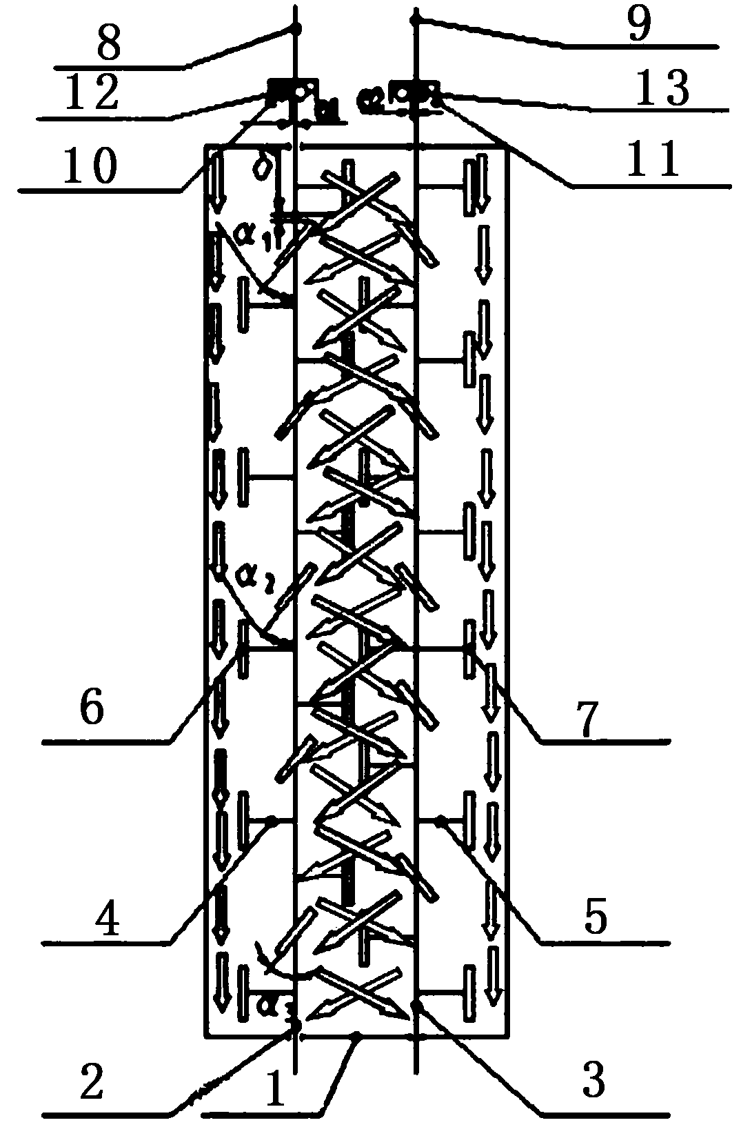
[0032] Such as figure 1 and figure 2 As shown, a double-horizontal shaft cross-recursive continuous vibration stirring device includes a mixing cylinder 1 and a vibration device. The mixing cylinder 1 is provided with a feed end and a discharge end, and the mixing cylinder 1 is equipped with a first A stirring shaft 2 and a second stirring shaft 3, the first stirring shaft 2 and the second stirring shaft 3 have the same structure, both ends of the first stirring shaft 2 and the second stirring shaft 3 are solid structures, the first stirring shaft 2 and the two ends of the second stirring shaft 3 are installed on the feed end and the discharge end respectively, the first stirring arm 4 is installed on the first stirring shaft 2, and the first stirring blade 6 is connected on the first stirring arm 4, The second stirring arm 5 is installed on the second stirring shaft 3, the second stirring arm 5 is connected with the second stirring blade 7, the structure of the first stirring...

Embodiment 2

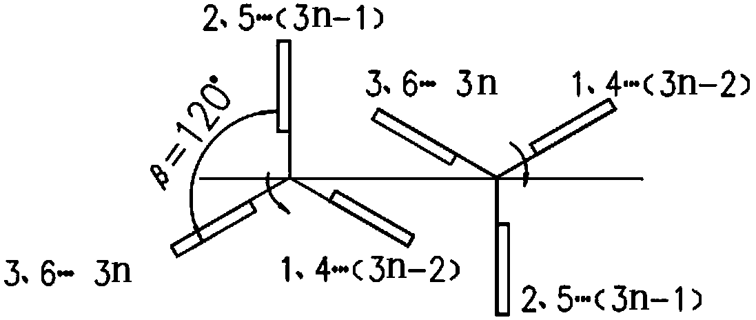
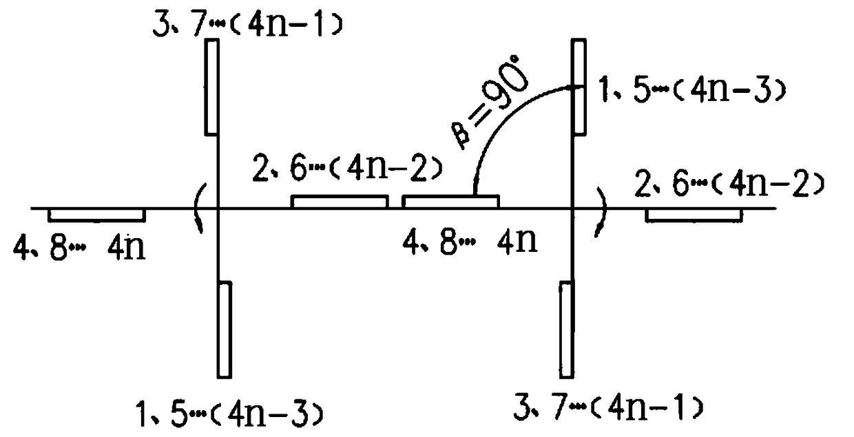
[0038] The difference between this embodiment and Embodiment 1 is: the installation angle α1 between the first stirring blade section 1 and the axis of the first stirring shaft = 45°, the installation angle between the first stirring blade section 2 and the axis of the first stirring shaft The included angle α2=55°, the installation angle α3=65° between the first stirring blade segment 3 and the axis of the first stirring shaft, the installation angle α′ between the second stirring blade segment 1 and the axis of the second stirring shaft 1=45°, the installation angle α′ between the second stirring blade segment 2 and the axis of the second stirring shaft 2=55°, the installation angle α′ between the second stirring blade segment 3 and the axis of the second stirring shaft 3=65°.

Embodiment 3

[0040] The difference between this embodiment and Embodiment 1 is: the installation angle α1 between the first stirring blade section 1 and the axis of the first stirring shaft = 50°, the installation angle between the first stirring blade section 2 and the axis of the first stirring shaft The included angle α2=60°, the installation angle α3=70° between the first stirring blade segment 3 and the axis of the first stirring shaft, the installation angle α′ between the second stirring blade segment 1 and the axis of the second stirring shaft 1=50°, the installation angle α′ between the second stirring blade segment 2 and the axis of the second stirring shaft 2=60°, the installation angle α′ between the second stirring blade segment 3 and the axis of the second stirring shaft 3=70°.


PUM


Abstract

The invention relates to a twin-shaft stirring device, in particular to a continuous vibrating stirring device with twin-shaft cross-recursion that promotes material circulation and cross-propelling, prolongs the stirring time, and improves the stirring quality. The vibration shaft and the vibrator are respectively connected, and the two stirring shafts rotate in reverse synchronously. The stirring blades on the two stirring shafts are continuously distributed in a reverse spiral shape. The stirring blades on each stirring shaft are divided into three groups. There are three different installation angles between the stirring blade and the axis of the stirring shaft, and there are installation phase angles and axial gaps between adjacent stirring blades, or the stirring blades on the two stirring shafts are all ribbon-shaped, and the helix angle Decrease, the material circulates and advances between the two shafts, making the material flow movement in the mixing tank more reasonable and stable, ensuring continuous, uniform and powerful advancement of the material in the mixing tank, prolonging the mixing time, and improving the mixing quality and mixing efficiency.

Description

technical field [0001] The invention relates to a twin-horizontal-shaft stirring device, in particular to a continuous vibrating stirring device with double-horizontal shafts crossing and recursively advancing material circulation, prolonging the stirring time and improving the stirring quality. Background technique [0002] The twin-shaft continuous mixer is a continuous forced mixer. Compared with the batch mixer, it has the advantages of simple structure and high production efficiency, but because of its short mixing time, it has relatively high requirements for mixing quality. Mature, so it has become one of the development directions of mixing equipment. As the core part of the stirring equipment, the stirring device directly affects the stirring quality and stirring efficiency of the whole machine. When the mixer is working, the stirring shaft drives the stirring blade installed on it to rotate, forcing the material to move according to the predetermined track. The m...

Claims


Application Information

Patent Timeline
Patent Type & Authority Patents(China)
IPC IPC(8): B28C5/16B28C5/48
CPCB28C5/16B28C5/48
Inventor 赵利军李冠峰张良奇冯忠绪
Owner 德通智能科技股份有限公司
Why Eureka
Try Eureka