Submarine cable underwater synchronous paying-off underwater vehicle

A technology for submersibles and submarine cables, which is applied to instruments, cable laying ships, three-dimensional position/channel control, etc., can solve problems such as obstacles in laying links, increased risks, and large time consumption, and achieves a high degree of integration and automation. The effect of high and low laying tension

Active Publication Date: 2016-11-09
NORTHEAST DIANLI UNIVERSITY
View PDF7 Cites 21 Cited by
  • Summary
  • Abstract
  • Description
  • Claims
  • Application Information

AI Technical Summary

Problems solved by technology

[0003] However, although the submarine cable plays a pivotal role, its laying link is a major obstacle
The current submarine cable laying usually adopts the method of "walking and laying" by the cable laying ship. The whole process needs to accurately control the line corridor and the entry angle, which is not only slow, but also very difficult, and the construction often takes up a lot of manpower and material resources.
In addition, changing sea weather conditions often pose a huge threat to the project. Normal waves and strong winds will cause the cable laying ship to deviate from the track. , causing the submarine cable to deviate from the line corridor and even damage the submarine cable body. If it encounters strong winds at sea, the risk will increase sharply, which is very likely to lead to the failure of the entire project
Various deficiencies have greatly affected the development of submarine lines

Method used


Image

  • Submarine cable underwater synchronous paying-off underwater vehicle
  • Submarine cable underwater synchronous paying-off underwater vehicle
  • Submarine cable underwater synchronous paying-off underwater vehicle

Examples


Embodiment Construction

[0041] The present invention will be described in more detail below in conjunction with the accompanying drawings and specific examples.

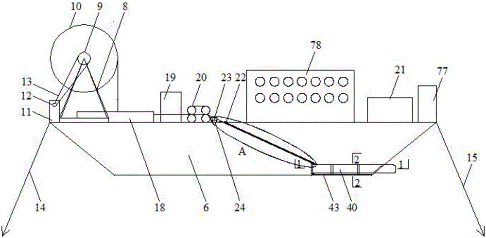
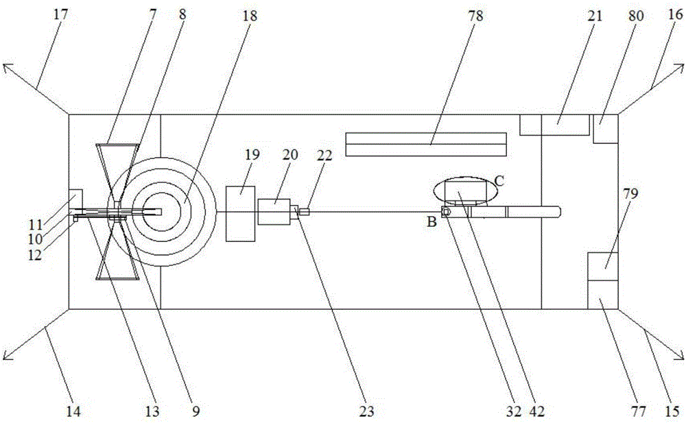
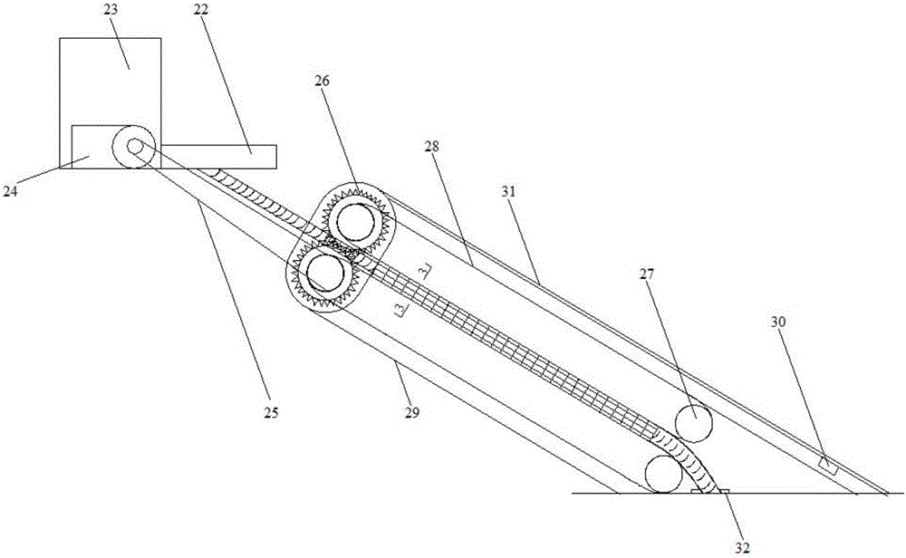
[0042] refer to Figure 1-11 , a submarine cable underwater synchronous release submersible, comprising a ship-borne mechanical system 1, a synchronous push system 2, a pneumatic launch system 3, a calculation central control system 4 and a towed submersible system 5, the synchronous push system 2, a pneumatic The launch system 3 and the calculation central control system 4 are all fixed on the shipboard mechanical system 1, and the towing stealth system 5 can move away from the hull.

[0043]The shipborne mechanical system 1 is used for the transportation of the synchronous push system 2, the pneumatic launch system 3, the towed submerged system 5 and the submarine cable, and can pull the submarine cable from the submarine cable storage box 18 to the synchronous push system 2, which includes a barge 6. Load-bearing plate 7, support frame ...


PUM


Abstract

The invention discloses a submarine cable underwater synchronous paying-off underwater vehicle which is characterized by comprising a shipborne mechanical system, a synchronous pushing system, a pneumatic launching system, a calculation center control system and a dragging and underwater-moving system. The technologies of electric automatization, aerodynamics, mechatronics and single chip microcomputer control and the like are integrated, underwater operation can be achieved, and the underwater vehicle is less affected by stormy waves; automatic detection and real-time paying-off can be achieved, the positioning precision is 0.5-3 m, the course accuracy is 0.01 degree, and a cable line corridor can be accurately controlled; cable laying is high in speed and can be controlled in real time, and the highest cable laying speed can reach 50 KM/h; the automation degree is high, and the number of construction staff is greatly decreased; the integration degree is high, and the whole process can be monitored; construction obstacles for the cable line corridor do not need to be cleared away, so that the environment is protected; all the systems can be recycled, and secondary investment is low; the systems operate synchronously, and the tension force of submarine cable laying is reduced; the line first-aid repair capability is high, and the submarine cable underwater synchronous paying-off underwater vehicle is suitable for line reconstruction work after seaquakes; and the structure is reasonable, and the performance is reliable.

Description

technical field [0001] The invention relates to the technical field of submarine cable laying, and relates to a submarine cable underwater synchronous release submersible. Background technique [0002] There are usually three types of power supply for coastal islands and mining platforms: diesel generators, spanning towers, and submarine cables. The capacity of generators is limited, which makes it difficult to meet large-scale power demand; the cost of erecting spanning towers is high, and windy and salty seaside areas are not suitable for tower operation; submarine cables have long life and mature technology, and are regarded as ideal power supply channels. In 2015, in the concept of "Global Energy Internet", intercontinental networking needs to cross the oceans such as Africa and Europe, Europe and North America, Australia and Asia, Asia and North America. The key to less. [0003] However, although submarine cables play a decisive role, their laying link is a major obs...

Claims


Application Information

Patent Timeline
Patent Type & Authority Applications(China)
IPC IPC(8): B63B35/04G05D1/10G08C17/02
CPCB63B35/04G05D1/10G08C17/02
Inventor 祝贺何旭严俊韬刘程李映桥于卓鑫王基琛王潇牛丽娜崔晓彤刘阳李秋澎
Owner NORTHEAST DIANLI UNIVERSITY
Why Eureka
Try Eureka