Aircraft Landing or Landing Electromagnetic Arresting Device
An electromagnetic and aircraft technology, applied in the direction of parking devices, etc., can solve the problems of large mass, low reliability, and complex structure of the landing assistance and arresting system, and achieve the effect of simple structure, high reliability, and small volume
- Summary
- Abstract
- Description
- Claims
- Application Information
AI Technical Summary
Problems solved by technology
Method used
Image
Examples
specific Embodiment approach 1
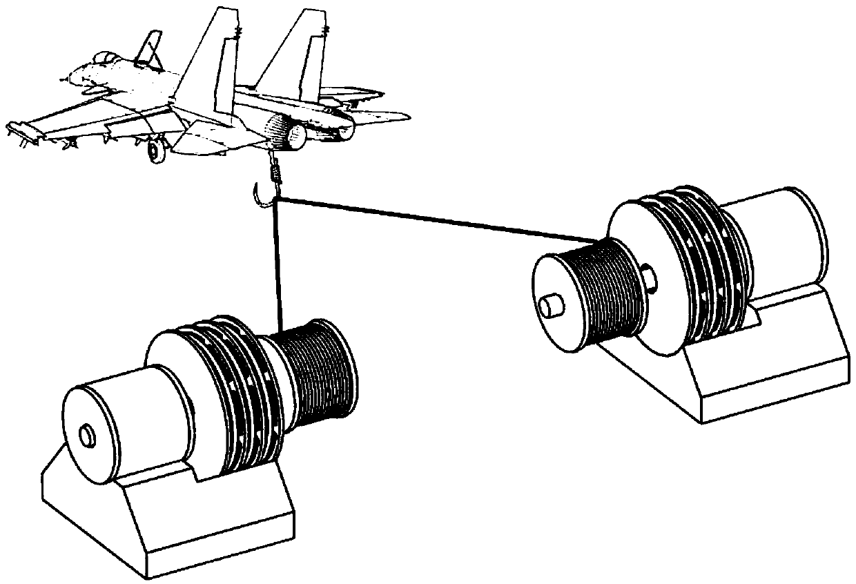
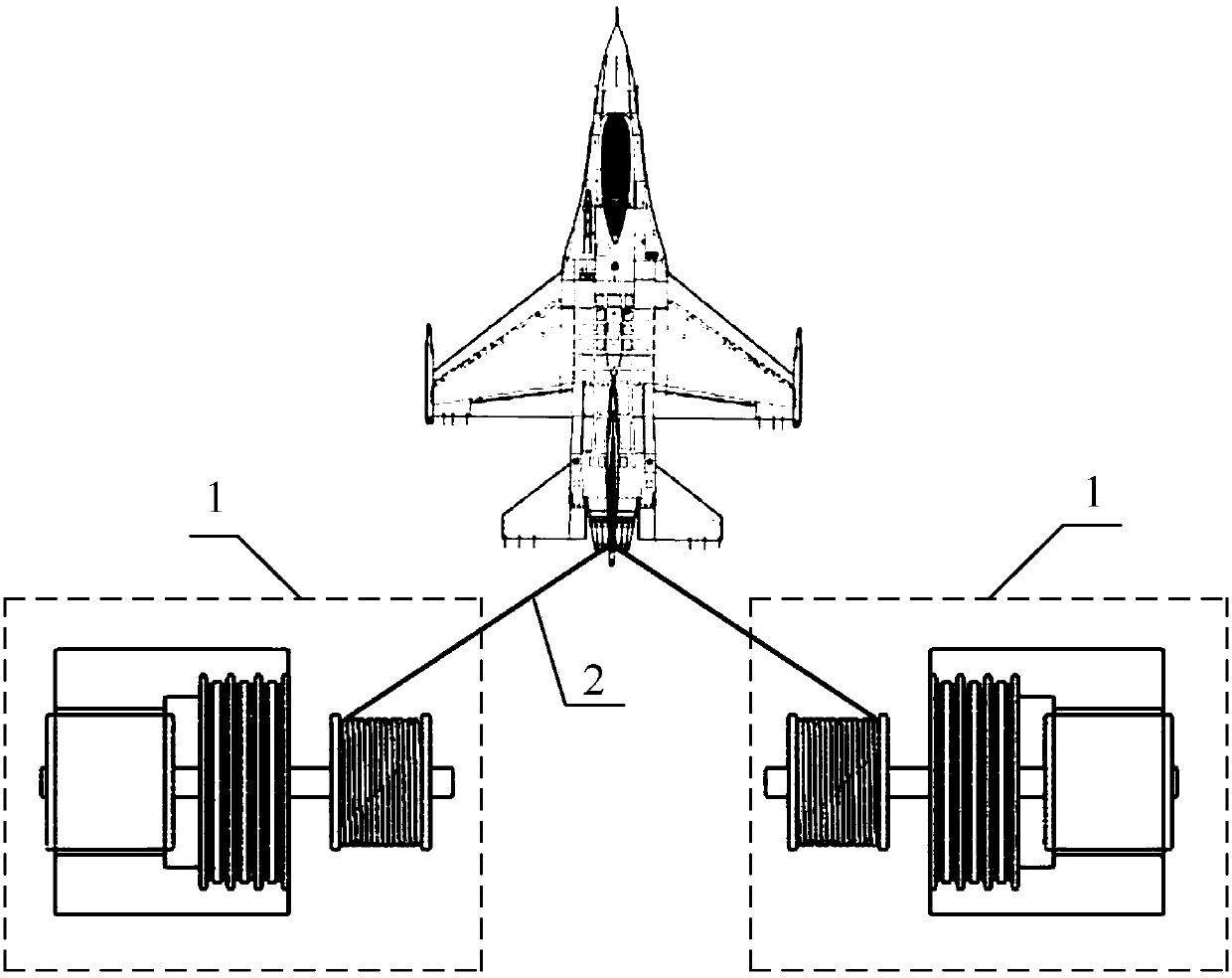
[0030] Specific implementation mode one: combine Figure 1 to Figure 3 To illustrate this embodiment, the aircraft landing or landing electromagnetic arresting device described in this embodiment includes two rotating electromagnetic arresters 1 with the same structure and an arresting cable 2;
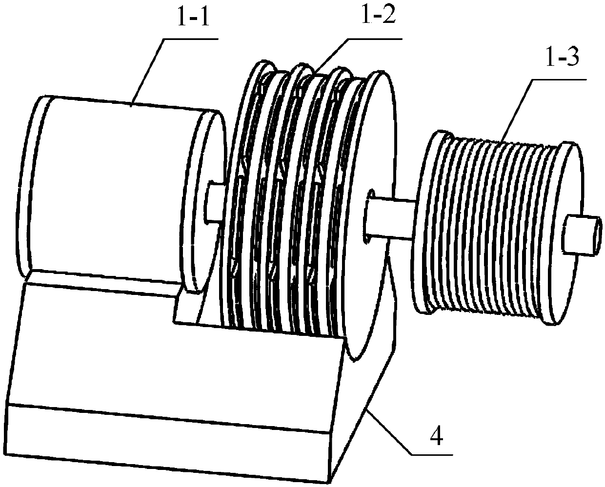
[0031] The rotary electromagnetic arrester 1 includes a rotary motor 1-1, a rotary eddy current brake 1-2, an arresting cable drum 1-3 and a motor drive controller, a rotary motor 1-1, a rotary eddy current brake 1-2 and an arresting cable The cable drum 1-3 share a rotating shaft, and the control signal output end of the motor drive controller is connected with the control signal input end of the rotating motor 1-1;
[0032] Two rotating electromagnetic arresters 1 are symmetrically arranged around the aircraft landing runway, and the two ends of the arresting cable 2 are respectively wound on the two arresting cable drums 1-3.
[0033] The working principle of the electromagnetic a...
specific Embodiment approach 2
[0034] Specific implementation mode two: combination figure 2 , Figure 4 and Figure 5 Describe this embodiment. This embodiment is a further limitation of the aircraft landing or landing electromagnetic arresting device described in Embodiment 1. In this embodiment, the rotary eddy current brake 1-2 is a multi-layer disc structure, including N+1 layers of stators and N layers of rotors, N is a positive integer, the stators and rotors are alternately distributed along the axial direction, forming a total of 2N layers of air gaps, and the axial length of each layer of air gaps is equal;
[0035] The stator includes a disk-shaped magnetic yoke plate and multiple permanent magnets, and the multiple permanent magnets are evenly distributed along the circumferential direction on the surface of the magnetic yoke plate;
[0036] The rotor is disc-shaped.
[0037] like figure 2 As shown, the casing of the rotating electrical machine 1-1 and the stator of the rotating eddy curre...
specific Embodiment approach 3
[0038] Specific implementation mode three: combination Figure 6 to Figure 8 Describe this embodiment. This embodiment is a further limitation of the aircraft landing or landing electromagnetic arresting device described in Embodiment 2. In this embodiment, the N-layer rotor adopts any one of the following three structures, two or three kinds;
[0039] The first structure: the rotor adopts a low-resistivity non-magnetic conductor plate (that is, a conductor plate, represented by A);
[0040] The second structure: the rotor adopts a magnetic material plate (that is, a magnetic plate, represented by B);
[0041] The third structure: the rotor includes two low-resistivity non-magnetic conductor plates and a disc-shaped magnetic conducting plate, and the two conducting plates are bonded on both sides of the magnetic conducting plate respectively (that is, the combination of the conducting plate and the magnetic conducting plate, denoted by C).
[0042] When the N rotors all ado...
PUM
 Abstract
Description
Claims
Application Information
 - R&D
- Intellectual Property
- Life Sciences
- Materials
- Tech Scout
- Unparalleled Data Quality
- Higher Quality Content
- 60% Fewer Hallucinations
Browse by: Latest US Patents, China's latest patents, Technical Efficacy Thesaurus, Application Domain, Technology Topic, Popular Technical Reports.
© 2025 PatSnap. All rights reserved.Legal|Privacy policy|Modern Slavery Act Transparency Statement|Sitemap|About US| Contact US: help@patsnap.com


