Accurate efficient enzyme deactivation device

A high-efficiency, enzyme-killing technology, applied in enzymology/microbiology devices, biochemical cleaning devices, enzyme production/bioreactors, etc. The effect of processing, small footprint and convenient operation

Active Publication Date: 2016-11-09
NINGBO BAIERMA BIOLOGICAL TECH CO LTD
View PDF9 Cites 0 Cited by
  • Summary
  • Abstract
  • Description
  • Claims
  • Application Information

AI Technical Summary

Problems solved by technology

At present, most of the steam generated by the steam engine is used to kill enzymes through steam pipes and heat and cold exchangers. These equipment take up a lot of space, and the process of killing enzymes is cumbersome, time-consuming and inefficient.

Method used


Image

  • Accurate efficient enzyme deactivation device

Examples


Embodiment Construction

[0011] The present invention is further described now in conjunction with accompanying drawing.

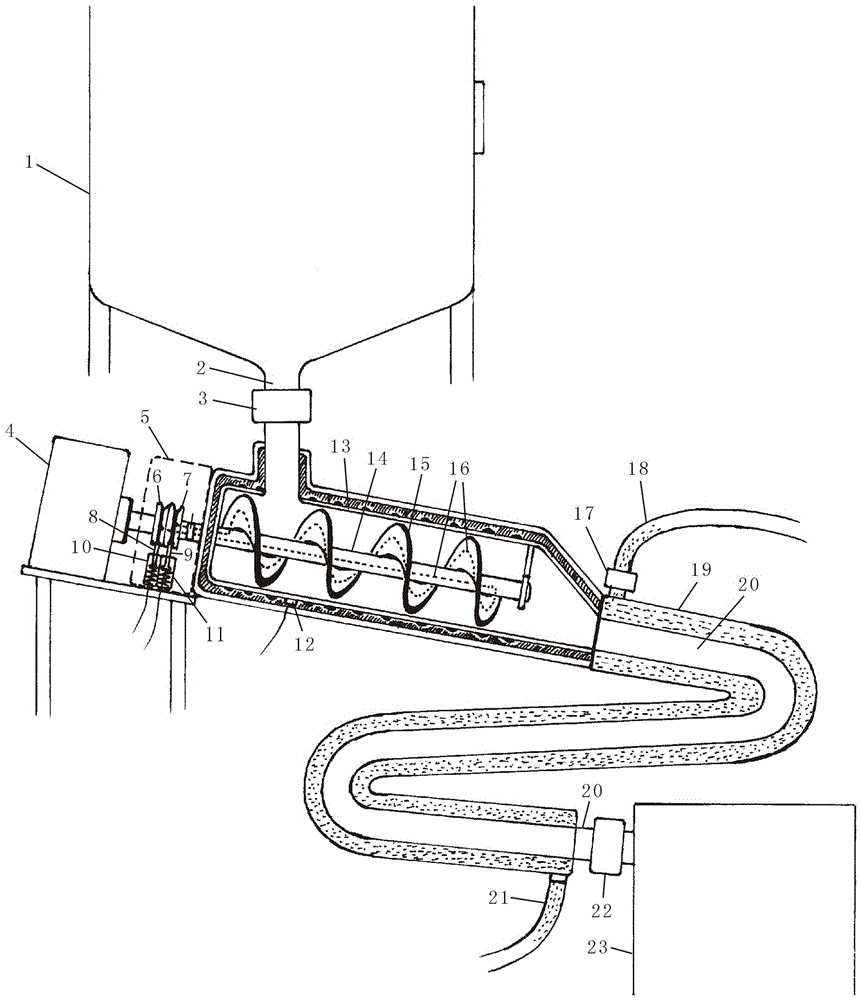
[0012] Such as figure 1 As shown in the figure, 1. Enzymolysis tank, 2. Outlet pipe, 3. The first solenoid valve, 4. Motor, 5. Safety box, 6. The first sheave, 7. The second sheave, 8. The first sheave One conductive rod, 9. the second conductive rod, 10. the first insulating tube, 11. the second insulating tube, 12.

[0013] Temperature sensor, 13. heating cylinder, 14. rotating shaft, 15. auger blade, 16. first heating pipe, 17. second solenoid valve, 18. tap water pipe, 19. cooling pipe, 20. feeding pipe, 21 . Outlet pipe, 22. Pump, 23. Storage tank.

[0014] The discharge pipe 2 of the enzymolysis tank 1 arranged on the ground or on the wall is provided with a first electromagnetic valve 3; the discharge pipe 2 is connected with the heating cylinder 13, and the outlet of the heating cylinder 13 is connected The feeding pipe 20 is connected to the feeding pipe 20, which is c...


PUM


Abstract

The invention provides an accurate efficient enzyme deactivation device. A discharge tube of an enzymatic vessel is connected with a heating barrel with a heating auger; the right end of a rotating shaft of the auger is connected with a hanging bracket in the heating barrel; the left end of the rotating shaft penetrates through the heating barrel and a safety box, and then is connected with a shaft of a motor; the rotating shaft positioned in the safety box is provided with a first grooved pulley and a second groove pulley which are provided with a first conductive ring and a second conductive ring respectively; and the first conductive ring and the second conductive ring are in contact with a first conductive bar and a second conductive bar on a first insulating tube and a second insulating tube. A first conductive wire and a second conductive wire which are arranged on the first conductive ring and the second conductive ring are connected with a first heating tube through connectors in the rotating shaft, and the heating tube is arranged in a cavity of blades and the rotating shaft of the auger. A temperature sensor and a second heating tube are arranged on the outer wall of the heating barrel. A conveying tube with a pump is arranged between the heating barrel and a storage barrel, and is arranged in a cooling tube. A running water tube with a second electromagnetic valve and a water outlet tube are arranged on the cooling tube. A first electromagnetic valve, the second electromagnetic valve, the first conductive bar, the second conductive bar, the second heating tube, the motor, the pump and the sensor are connected with a controller on the outer wall of the enzymatic vessel through wires.

Description

technical field [0001] The invention relates to an enzyme inactivating device, in particular to an accurate and efficient enzyme inactivating device. Background technique [0002] After the material body in the enzymatic hydrolysis tank is released, it is necessary to quickly and instantaneously inactivate the enzyme, and to quickly cool the material body to facilitate subsequent processing of the material body. Most of the enzymes are now inactivated by the steam generated by the steam engine through steam pipes and heat and cold exchangers. These devices take up a lot of space, and the enzyme inactivation process is cumbersome, time-consuming and inefficient. Contents of the invention [0003] The purpose of the present invention is to provide a precise and efficient enzyme inactivation device to solve the above problems. [0004] The technical solution adopted in the present invention is: the discharge pipe of the enzymolysis tank arranged on the ground or wall is prov...

Claims


Application Information

Patent Timeline
Patent Type & Authority Applications(China)
IPC IPC(8): C12M1/00C12M1/40
CPCC12M21/18C12M47/00C12M47/08C12M47/20
Inventor 钱金宏陈科卢晓会钱杰瑞黄云琦金芹钱勇黄代勇
Owner NINGBO BAIERMA BIOLOGICAL TECH CO LTD
Why Eureka
Try Eureka