
Electroplating clip conductive type reel-to-reel vertical continuous electroplating equipment

A vertical continuous electroplating, roll-to-roll technology, applied in the direction of current conduction device, cleaning/polishing of conductive pattern, electrode, etc. Ground space, ensure good conductive contact, and wide application range

Active Publication Date: 2016-11-09
GREAT CHIEFTAIN ELECTRONICS MACHINERY
View PDF7 Cites 11 Cited by
  • Summary
  • Abstract
  • Description
  • Claims
  • Application Information

AI Technical Summary

Problems solved by technology

This will cause delamination on the board surface after plating (it can be seen after professional slicing, and this phenomenon is not allowed in this process)
[0010] Third, the above-mentioned roller conductive vertical electroplating equipment has no moving conveying mechanism in the middle, only the conveying and rotating mechanism at the two ends of unwinding and rewinding. If the PCB span is too long, it needs to be straightened so that the pulling force will increase and it is easy to break off.

Method used


Image

  • Electroplating clip conductive type reel-to-reel vertical continuous electroplating equipment
  • Electroplating clip conductive type reel-to-reel vertical continuous electroplating equipment
  • Electroplating clip conductive type reel-to-reel vertical continuous electroplating equipment

Examples


Embodiment Construction

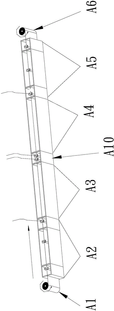
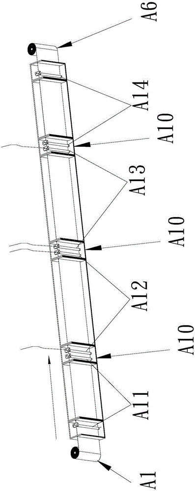
[0067] like Figure 5 to Figure 23 As shown, the electroplating clip conductive roll-to-roll vertical continuous electroplating equipment of the present invention is composed of an unwinder 1 , a pre-processing section 2 , an electroplating section 3 , a post-processing section 4 and a winding machine 5 . Wherein, the pre-treatment section 2, the electroplating section 3 and the post-treatment section 4 are all installed between the unwinder 1 and the winder 5 and arranged in sequence according to the direction from the unwinder 1 to the winder 5. The electroplated flexible circuit board FPC is released by the unwinder 1 and rewound into a roll by the winder 5, and the electroplated flexible circuit board FPC moving from the unwinder 1 to the winder 5 is released by the unwinder 1 and the winder. The machine 5 is tensioned in a plane, and the pre-treatment section 2, the electroplating section 3 and the post-processing section 4 sequentially perform electroplating pre-treatmen...


PUM

PropertyMeasurementUnit
thicknessaaaaaaaaaa

Abstract

The invention discloses electroplating clip conductive type reel-to-reel vertical continuous electroplating equipment. The electroplating clip conductive type reel-to-reel vertical continuous electroplating equipment is composed of an unreeling machine, a front treatment section, an electroplating section, a rear treatment section and a reeling machine, wherein the electroplating section is provided with an electroplating cylinder, a plurality of cathode clamps, a clamp drive control device, a positive plate and a power source system; the clamp drive control device can drive the cathode clamps to be opened before entering the incoming end position, closed when moving from the incoming end position to the outgoing end position, and opened after leaving from the outgoing end position; the power source system is provided with a direct current power source, a cathode conductive mechanism and a positive wire; and the cathode clamps are electrically connected with the cathode of the direct current power source through the cathode conductive mechanism when moving from the incoming end position to the outgoing end position. The electroplating clip conductive type reel-to-reel vertical continuous electroplating equipment has the advantages of being high in electroplating uniformity, wide in application range of electroplated flexible circuit boards, small in occupied space, capable of electroplating the electroplated flexible circuit boards smaller in thickness, high in working safety and high in structural reliability, and the electroplated boards are not likely to have an electroplating layering phenomenon.

Description

technical field [0001] The invention relates to an electroplating clip conductive type roll-to-roll vertical continuous electroplating equipment. Background technique [0002] With the changes of the times and the advancement of science and technology, efficiency and precision are emphasized in everything, and the same is true for electroplating technology. The thickness of PCB in the industry is getting thinner and thinner, from hard board to thin board to soft board or FPC. The electroplating industry puts forward higher requirements, with smaller footprint, higher production capacity, thinner substrate, good electrical conductivity during the electroplating process, high plating uniformity, and electroplating equipment with more varieties of electroplating are more favored by customers. The PCB electroplating process can be mainly divided into three parts: the pre-processing section for pre-processing the substrate, the copper plating section for electroplating the subst...

Claims


Application Information

Patent Timeline
Patent Type & Authority Applications(China)
IPC IPC(8): C25D19/00C25D17/08C25D7/00
CPCC25D7/00C25D17/00C25D17/08C25D5/08C25D5/48C25D7/0614C25D17/005C25D17/007C25D17/06C25D17/12C25D21/06C25D21/12H05K3/188H05K3/26
Inventor 邓高荣
Owner GREAT CHIEFTAIN ELECTRONICS MACHINERY
Learn More