
Concrete beam-STC combination bridge-face structure and construction method thereof

A technology of concrete beams and composite bridge decks, applied in bridges, bridge parts, bridge construction, etc., can solve the problems of large differences between physical properties and structural properties, poor bonding, and no consideration of STC, etc., to improve fatigue resistance Destructive ability, small thickness, and the effect of avoiding erosion damage

Inactive Publication Date: 2016-11-09
HUNAN ZHONGLU HUACHENG BRIDGE TECH CO LTD
View PDF11 Cites 2 Cited by
  • Summary
  • Abstract
  • Description
  • Claims
  • Application Information

AI Technical Summary

Problems solved by technology

[0006] However, due to the high cost of STC and the difficulty in construction, it is generally paved directly on the steel plate deck of a steel bridge in the form of a thin layer, and the physical and structural properties of the STC and the concrete surface are quite different, and the interaction between them Not very good, so those skilled in the art have never considered how to effectively apply STC to concrete bridge decks or pavements, there is a blank for this application, so there is basically no practice of applying STC to concrete pavements and concrete bridge decks in the prior art

Method used


Image

  • Concrete beam-STC combination bridge-face structure and construction method thereof
  • Concrete beam-STC combination bridge-face structure and construction method thereof

Examples


Embodiment 1

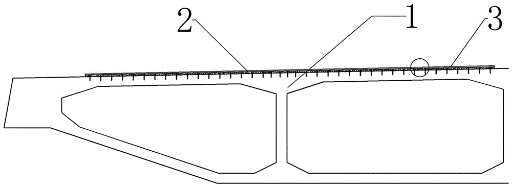
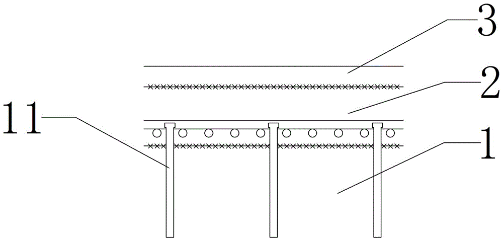
[0081] Embodiment 1, the present invention comprises the beam top layer 1, the STC layer 2 and the studs 11 fixedly connected with the beam top layer 1 and the STC layer 2 respectively at both ends, the beam top layer 1 body is a concrete structure layer; on the beam top layer 1 upper surface Fixing holes are arranged and distributed according to the principle of mechanics, and pegs 11 are fixed in each fixing hole. The upper part of the pegs 11 protrudes from the upper surface of the beam top layer 1, and the height of the upper part of the pegs 11 protruding from the upper surface of the beam top layer 1 is smaller than the STC layer 2. The thickness of the beam top layer 1 is laid on the STC layer 2, so that the two ends of the studs 11 are fixedly connected with the beam top layer 1 and the STC layer 2 respectively, forming an integral concrete beam-STC composite bridge deck structure, see Figure 1 to Figure 2 .

[0082] The stud 11 of the present invention can adopt the ...

Embodiment 2

[0084] Embodiment 2, the beam top layer 1 of the present invention is the top plate of the bridge, and the spacing of the fixing holes arranged on the upper surface of the beam top layer 1 is scientifically designed and arranged according to the principles of mechanics. The preferred spacing between the fixing holes is 10-40 cm, and the best The best spacing is 15~30cm to ensure that all parts of the top layer of the beam are evenly stressed. The pegs 11 can be implanted in the top layer of the beam 1 in a manner similar to planting bars, that is, firstly drill fixing holes on the upper surface of the top layer 1 of the beam, and then fill the fixing holes with inorganic glue, the inorganic glue includes cement inorganic glue with good durability etc., to ensure that it is consistent with the life of the bridge, and then the peg 11 is inserted into the fixing hole, and the peg 11 is firmly connected with the top layer of the beam through the adhesive. refer to Figure 1 to Fi...

Embodiment 3

[0085] Embodiment 3, the STC layer 2 of the present invention includes steel mesh and ultra-high-performance concrete, and the steel mesh can be directly laid on the upper surface of the beam top layer 1, and the steel bars in the steel mesh can also be connected or overlapped with the pegs 11, The ultra-high-performance concrete completely covers the studs 11 and the entire reinforcement mesh on the upper surface of the top layer 1 of the protruding beam. The spacing between the reinforcement bars in the reinforcement mesh can be equal, and the reinforcement bars in the reinforcement mesh can also be formed perpendicular to each other. Mesh, the ultra-high performance concrete wraps the studs 11 and the steel mesh, so that the ultra-high performance concrete completely covers the studs 11 and the steel mesh to form a whole, see Figure 1 to Figure 2 , and the rest are combined with any other embodiment of the present invention or two or more embodiments.


PUM


Abstract

The invention discloses a concrete beam-STC combination bridge-face structure and a construction method thereof. The technical problems that an existing structure is unreasonable, the material performance is free of high quality, the construction technology is low in efficiency, and the structure function is incomplete are mainly solved. The concrete beam-STC combination bridge-face structure and the construction method thereof in the technical scheme are characterized in that the concrete beam-STC combination bridge-face structure comprises a beam top layer (1), an STC layer (2) and bolt nails (11), wherein the two ends of the bolt nails (11) are fixedly connected with the beam top layer (1) and the STC layer (2) respectively, and a body of the beam top layer (1) is a concrete structure layer; the bolt nails (11) are implanted into the upper surface of the beam top layer (1), the upper portions of the bolt nails (11) protrude out of the upper surface of the beam top layer (1), and the height, protruding out of the upper surface of the beam top layer (1), of the upper portions of the bolt nails (11) is smaller than the thickness of the STC layer (2); the STC layer (2) is laid on the beam top layer (1) to form the whole concrete beam-STC combination bridge-face structure. The concrete beam-STC combination bridge-face structure is mainly applied to bridge engineering construction and later stage maintenance and repairing construction of bridge engineering.

Description

technical field [0001] The invention relates to a concrete beam-STC composite bridge deck structure and a construction method thereof, in particular to a bridge deck structure system formed by combining a concrete beam top panel and super-high toughness concrete (STC). Background technique [0002] At present, concrete beams are widely used on bridges with various spans, and are very important bridge structures for public transportation tasks. However, in the traffic operation of the bridge deck pavement structure of this type of beam, there have been many, very common and serious structural damage problems so far, which to a large extent have an adverse impact on public transportation and cause social and economic losses . [0003] There are currently three main types of concrete girder deck pavement structures, namely concrete structure, asphalt structure, and combined structure of concrete lower layer + asphalt upper layer. [0004] At present, there are common and seri...

Claims


Application Information

Patent Timeline
Patent Type & Authority Applications(China)
IPC IPC(8): E01D19/12E01D21/00
CPCE01D19/125E01D21/00
Inventor 邵旭东胡建华毛志坚张法彭力军
Owner HUNAN ZHONGLU HUACHENG BRIDGE TECH CO LTD
Learn More