
A temperature difference driven turbine

A technology of temperature difference and turbine, which is applied in the direction of automatic clutch, machine/engine, mechanism for generating mechanical power, etc. It can solve the problems of reducing the work efficiency of the temperature difference to rotate the kinetic energy conversion device, etc., to achieve a large temperature difference and avoid the leakage of the working medium , the effect of high work efficiency

Active Publication Date: 2018-12-11
SOUTH CHINA UNIV OF TECH +1
View PDF11 Cites 0 Cited by
  • Summary
  • Abstract
  • Description
  • Claims
  • Application Information

AI Technical Summary

Problems solved by technology

Although the warm seawater on the surface of the ocean as a heat source has a wide range of sources, because this thermoelectric power generation system needs to consume part of the electric energy generated by the system on the working energy consumption of the pumping water pump of the surface seawater, thereby reducing the temperature difference energy and rotating the kinetic energy conversion device The efficiency of work, this defect limits the development of thermoelectric power generation in the direction of high efficiency and low cost to a certain extent

Method used


Image

  • A temperature difference driven turbine
  • A temperature difference driven turbine
  • A temperature difference driven turbine

Examples


Embodiment Construction

[0039] In order to better understand the present invention, the present invention will be further described below in conjunction with the accompanying drawings, but the embodiments of the present invention are not limited thereto. The diameter of the joint between the shrinking cone-shaped rotary body shell part of the inner shell 7 and the cylindrical cavity is consistent with the diameter of the cavity.

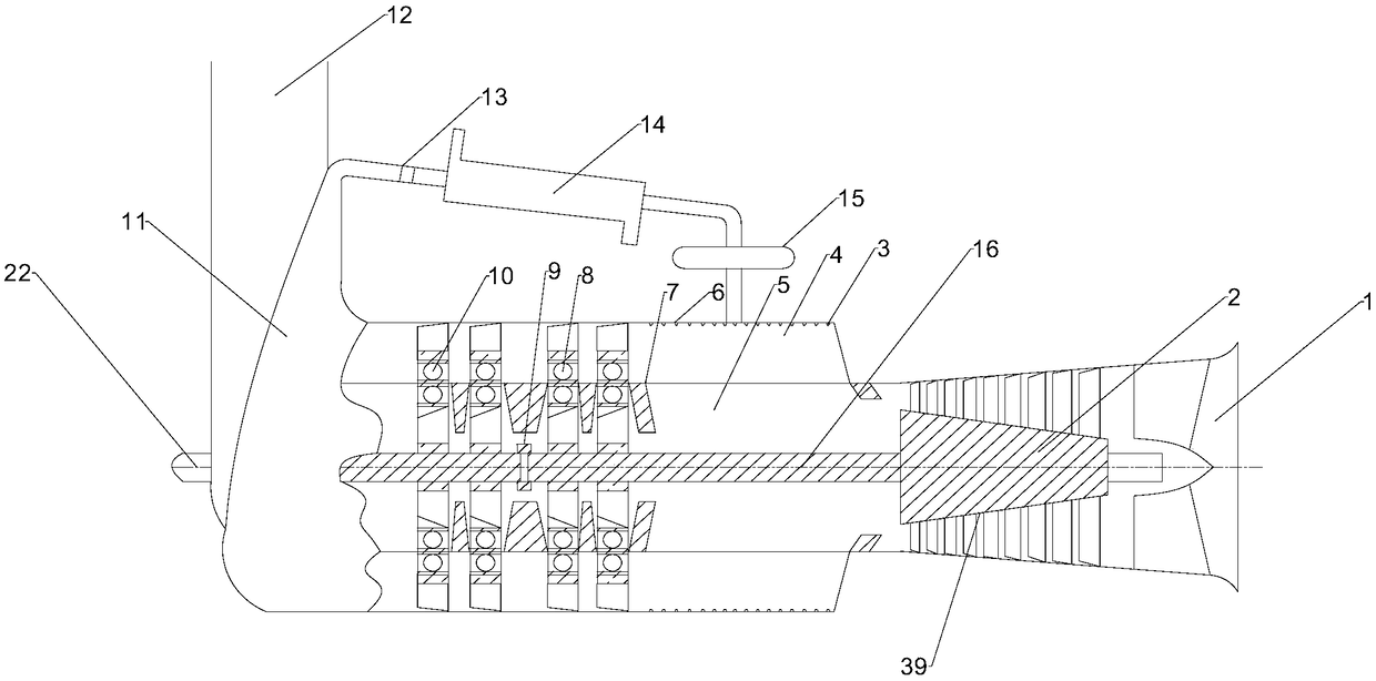
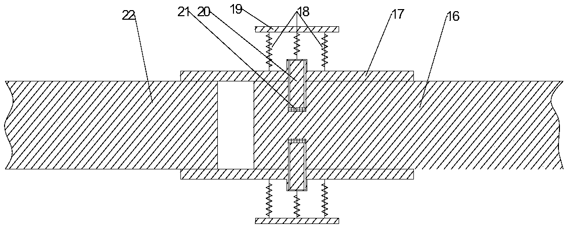
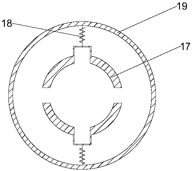
[0040] Such as figure 1 , 4 As shown, a temperature difference driven turbine includes a hot air inlet 1, a hot compressor 2, a working medium nozzle 3, an outer housing space 4, an inner housing space 5, an outer housing 6, an inner housing 7, a low-pressure turbine 8, and a clutch 9. High-pressure turbine 10, guide pipe 11, exhaust duct 12, compressor 13, condensation pipe 14 and storage device 15, compressor main shaft 16, high-pressure turbine main shaft 22; the outer shell 6 is a cylindrical cavity, and the inner shell The body 7 protrudes from the outer shell 6, and...


PUM


Abstract

The invention discloses a temperature difference driving turbine which comprises a gas compressor, a low-pressure turbine body, a high-pressure turbine body, a clutch, an inner shell, an outer shell, a compressor and a storage device. The low-pressure turbine body and the high-pressure turbine body are each composed of an inner disc face and an outer impeller ring which are coaxial and are made of aluminum alloys, wherein torque transmission between each inner disc face and the corresponding outer impeller ring is completed through a magnetic transmission technology. The appearance of a gas compressor body is designed to be in a circular truncated cone shape, and the diameters of gas compression impellers which are arranged in the axial direction are changed according to the trend of a contracted cone shape. The clutch is used for achieving the mechanical relation of disengaging or engaging between a main shaft of the gas compressor and a main shaft of the high-pressure turbine body under the combined effect of compression springs, shaft holding plates, sliding blocks and other mechanisms. According to the temperature difference driving turbine, ocean temperature difference energy generated through the manner that air is adopted as a heat source and seawater of the deep layer is adopted as a cold source is adopted for driving the low-pressure turbine body and the high-pressure turbine body to rotate, and therefore a temperature difference power generator can be driven to generate power. By the adoption of the temperature difference driving turbine, the purpose of developing ocean temperature difference energy with high efficiency and low cost can be achieved.

Description

technical field [0001] The invention relates to a turbine, in particular to a temperature-difference-driven turbine, in particular to a temperature-difference drive device composed of air as a heat source and deep seawater as a cold source. Background technique [0002] There is a temperature difference between the warm seawater or hot air on the surface of the ocean as a heat source and the deep cold seawater as a cold source, which contains abundant heat energy resources. This temperature difference energy has the characteristics of being reproducible, pollution-free, not changing with time, and relatively stable. By converting the energy generated by the ocean temperature difference into rotational motion through a certain energy conversion device, and then driving the thermoelectric generator to generate electricity, it can provide large-scale and stable power supply for some artificial structures on the sea and island areas. Designing and developing a high-efficiency t...

Claims


Application Information

Patent Timeline
Patent Type & Authority Patents(China)
IPC IPC(8): F03G7/04F01K25/10F01D15/10F01D15/08F16D43/18
CPCF01D15/08F01D15/10F01K25/10F03G7/04F16D43/18F16D2043/145Y02E10/30
Inventor 吴家鸣梁严刘书栋曾嘉城李林华卢立桦
Owner SOUTH CHINA UNIV OF TECH
Learn More