
Capillary eddy heat exchanger

A technology of heat exchanger and capillary tube, which is applied in the field of capillary vortex heat exchanger, can solve the problems of occupying branch tube space, shortening the life of equipment, and affecting the heat exchange effect, so as to enhance the heat exchange effect, avoid equipment damage, and improve equipment efficiency Effect

Pending Publication Date: 2016-11-09
山东绿泉空调科技有限公司
View PDF1 Cites 3 Cited by
  • Summary
  • Abstract
  • Description
  • Claims
  • Application Information

AI Technical Summary

Problems solved by technology

After a period of market research and user feedback, it was found that in the application process of the above-mentioned patented technology, there are serious problems in the flow-blocking obstacles set around the spirally coiled branch pipes to fill large gaps. When the material is too soft, it will deform and occupy the space around the branch pipe, resulting in a reduction in the heat transfer area and affecting the heat transfer effect; when the material of the large-gap flow blocking obstacle is too hard, after a period of use, not only scale will accumulate on the surface, but it will also be easily corroded by alkali Damaged, resulting in leakage of inner filling
[0005] After a period of use, due to regional water supply pressure differences or water outages, the condensing medium compressor is idling, which is likely to cause dry burning or overcooling of the heat exchanger, and ultimately shorten the life of the equipment

Method used


Image

  • Capillary eddy heat exchanger
  • Capillary eddy heat exchanger
  • Capillary eddy heat exchanger

Examples


Embodiment Construction

[0041] The present invention will be further described in detail below in conjunction with the accompanying drawings and specific embodiments.

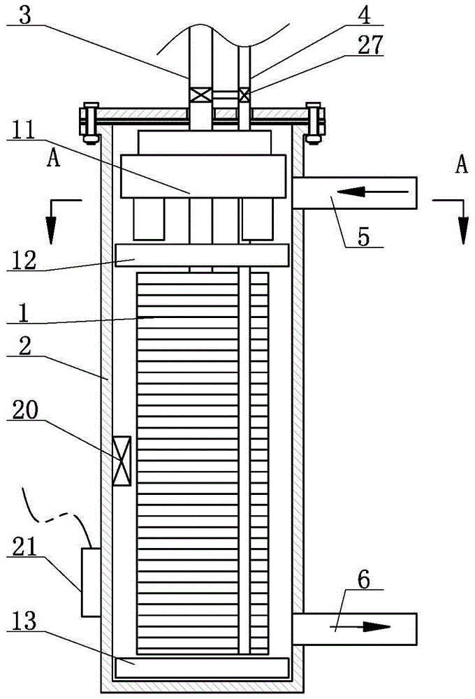
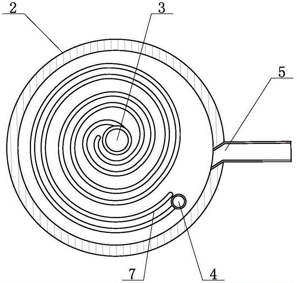
[0042] likefigure 1 and 2 As shown, a capillary vortex heat exchanger according to the present invention includes a casing 2, a cooling medium circulation pipeline is arranged in the casing 2, and water inlets 5 and The water outlet 6 and the water inlet 5 are located above the water outlet 6 . The cooling medium circulation pipeline includes an input pipe 3 and an output pipe 4, and several branch pipes 1 with both ends connected to the input pipe 3 and the output pipe 4 are arranged in parallel, and the branch pipe 1 is spirally wound around the input pipe 3 or the output pipe 4; The water inlet direction of the water port 5 and the casing 2 form an angle of 0-45 degrees. The rotation direction of the incoming water is opposite to the flow direction of the cooling medium. The water circulation is opposite to the cooling medium ci...


PUM


Abstract

The invention discloses a capillary eddy heat exchanger and belongs to the field of ground source heat pump devices. The capillary eddy heat exchanger is characterized by comprising a main case, a cooling-medium circulation line is arranged in the main case, a water inlet and a water outlet are respectively arranged in side walls of two ends of the main case, and the water inlet is located above the water outlet; the cooling-medium circulation line comprises an inlet pipe and an outlet pipe, a plurality of branch pipes with two ends communicated with the inlet pipe and the outlet pipe are arranged in parallel, and the branch pipes are spirally wound the inlet pipe or the outlet pipe from the periphery; the water inflowing direction of the water inlet forms a 0-45-degree included angle with the main case; water-inflowing rotation direction is opposite to the flowing direction of a cooling medium, and water circulation is opposite to circulation flowing direction of the cooling medium, and with over-entering and down-out water flow, more sufficient heat exchange is achieved. Besides, the capillary eddy heat exchanger is provided with a guiding device, a supporting device and a protecting device, hermetic heat exchanging space enclosed by upper and lower separating sealing rubber gaskets and the inner wall of the main case enables the capillary eddy heat exchanger to be more compact in structure, practical, safe and convenient and long in service life.

Description

technical field [0001] The invention belongs to the field of ground source heat pump devices, and in particular relates to a capillary vortex heat exchanger. Background technique [0002] The traditional ground energy air conditioning heat exchanger generally adopts one to three linear cooling medium input and output pipes in the casing, which are used to transport the cooling medium to contact the groundwater entering the casing for heat exchange and cooling, and then discharge the groundwater to cool down. The cooling medium continues to circulate to the air outlet of the air conditioner, and the wind wheel blows cold air to adjust the temperature in the living room. The structure of the traditional heat exchanger is limited, and the heat exchange efficiency is low, which leads to poor cooling effect of the air conditioner. [0003] A scroll tube heat exchanger applied by "Nanjing Goode Di Environmental Technology Co., Ltd." on March 28, 2014, by setting several scroll tu...

Claims


Application Information

Patent Timeline
IPC IPC(8): F25B39/00F28F11/00F28F9/013F28F27/00F28F9/22F28F19/01
CPCF25B39/00F28F9/013F28F9/22F28F11/00F28F19/01F28F27/00F28F2265/30F28F2265/10F28F2009/222
Inventor 张行刚
Owner 山东绿泉空调科技有限公司
Learn More