Supercharge Your Innovation With Domain-Expert AI Agents!

Direct air cooling system with peak cooling device

A peak cooling and air cooling system technology, applied to steam/steam condensers, lighting and heating equipment, etc., can solve the problems of high investment costs, reduce exhaust steam flow, increase heat exchange temperature difference and output, and reduce total pressure drop Effect

Inactive Publication Date: 2016-11-09
SHUANGLIANG ECO ENERGY SYST CO LTD
View PDF7 Cites 7 Cited by
  • Summary
  • Abstract
  • Description
  • Claims
  • Application Information

AI Technical Summary

Problems solved by technology

[0005] 1) Adding pipes and valves on the exhaust pipe to lead the exhaust steam into the water-cooled condenser, the investment cost is high;

Method used


Image

  • Direct air cooling system with peak cooling device

Examples


Embodiment 1

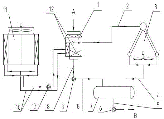
[0018] see figure 1 , figure 1 It is the schematic diagram of embodiment 1, and the direct air-cooling system of band peak cooling device of the present invention comprises exhaust device 1, exhaust pipeline 2, air-cooled condenser 3 and peak cooling device (by water cooling condenser heat exchanger 12, cooling Tower 11, circulating water pipeline 10 and circulating water pump 13), the water-cooled condenser heat exchanger 12 is arranged in the steam exhaust device 1, the condensed water tank 7 is added to the system, and the air-cooled condenser 3 passes through the first condensed water pipeline 4 is connected with the condensed water tank 7, and the exhaust device 1 is connected with the condensed water tank 7 through the second condensed water pipeline 8. The cooling tower 11 is a dry air cooling tower, or a wet closed evaporative cooling tower, or a wet open cooling tower. The cooling tower 11 is connected with the water cooling condenser heat exchanger 12 in the exhaus...


PUM


Abstract

The invention relates to a direct air cooling system with a peak cooling device. The direct air cooling system is used for the condensation process of steam turbine exhaust steam of a thermal power plant. The direct air cooling system comprises a steam exhaust device (1), a steam exhaust pipeline (2), an air-cooled condenser (3) and the peak cooling device. The direct air cooling system is characterized in that the peak cooling device comprises a water-cooled condenser heat exchanger (12), a cooling tower (11) and a circulating water pipeline (10); the water-cooled condenser heat exchanger (12) is arranged in the steam exhaust device (1), so that the steam exhaust device achieves a steam condensation function; the water-cooled condenser heat exchanger (12) is connected with the cooling tower (11) through the circulating water pipeline (10); and the system is additionally provided with a condensate water tank (7) for storing condensate water, the air-cooled condenser (3) is connected with the condensate water tank (7) through a first condensate water pipeline (4), and the steam exhaust device (1) is connected with the condensate water tank (7) through a second condensate water pipeline (8). The direct air cooling system has the beneficial effects that the pressure drop of dead steam in the steam exhaust device and the steam exhaust pipeline is reduced, a flow diversion pipeline and a valve of the peak cooling device are omitted, and the invested cost of the system is reduced.

Description

technical field [0001] The invention relates to a direct air cooling system with a peak cooling device, which is used for the condensation process of steam turbine exhaust in a thermal power plant. Background technique [0002] In the process of thermal power generation, the exhaust steam discharged from the low-pressure cylinder of the steam turbine needs to be condensed into water and then sent back to the boiler for recycling. In order to save water resources, many power plants use direct air cooling system to condense exhaust steam. [0003] At present, the direct air-cooling system is composed of an exhaust device, an exhaust pipe, an air-cooled condenser, and a condensate pipe. After the exhaust steam from the low-pressure cylinder of the steam turbine enters the exhaust device, it is introduced into the air-cooled condenser through the exhaust pipe to be condensed into water, and then returns to the exhaust device. The exhaust device has the function of storing cond...

Claims


Application Information

Patent Timeline
Patent Type & Authority Applications(China)
IPC IPC(8): F28B1/02F28B7/00F28B9/08
CPCF28B1/02F28B7/00F28B9/08
Inventor 薛海君江瀚
Owner SHUANGLIANG ECO ENERGY SYST CO LTD
Features
  • R&D
  • Intellectual Property
  • Life Sciences
  • Materials
  • Tech Scout
  • Unparalleled Data Quality
  • Higher Quality Content
  • 60% Fewer Hallucinations
Learn More