Measuring system and method for vibration parameters of scanning galvanometer

A technology for scanning galvanometers and vibration parameters, which is applied to measuring devices, measuring ultrasonic/sonic/infrasonic waves, instruments, etc. It can solve the problems of low frequency response, small angle measurement range, and affecting the dynamic performance of galvanometers, etc., to achieve anti-interference Strong ability, large angle measurement range, and stable optical path structure

Active Publication Date: 2022-03-25
XI'AN INST OF OPTICS & FINE MECHANICS - CHINESE ACAD OF SCI
View PDF8 Cites 0 Cited by
  • Summary
  • Abstract
  • Description
  • Claims
  • Application Information

AI Technical Summary

Problems solved by technology

[0004] The measurement of the vibration parameters of the existing galvanometer is mostly based on a high-precision tracking system to achieve non-contact measurement, but the angle measurement range of the system is not large, and the frequency response is low; while other measurement systems based on the principle of precision angle measurement, although The measurement speed is fast, the precision is high, and the ability to resist environmental interference is strong, but it is usually necessary to install auxiliary devices on the galvanometer, and the intervention of the auxiliary device will affect the dynamic performance of the galvanometer itself

Method used


Image

  • Measuring system and method for vibration parameters of scanning galvanometer
  • Measuring system and method for vibration parameters of scanning galvanometer
  • Measuring system and method for vibration parameters of scanning galvanometer

Examples


Embodiment Construction

[0053] The present invention will be described in detail below with reference to the accompanying drawings and specific embodiments.

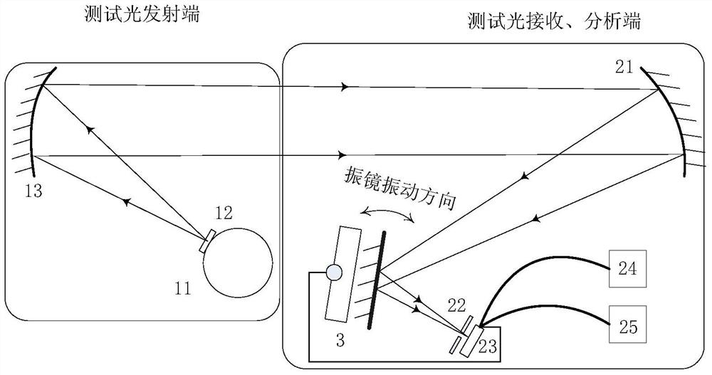
[0054] like figure 1 As shown, the measuring system for the vibration parameters of the scanning galvanometer provided by the present invention is composed of a measuring light emitting end and a measuring light receiving and analyzing end.

[0055] 1. Measuring the light emitting end

[0056]The measuring light emitting end includes an integrating sphere white light source 11 and a first off-axis parabolic mirror 13; a sine grating 12 is placed at the light outlet of the integrating sphere white light source 11, and the direction of the sine grating 12 is the same as the vibration direction of the scanning galvanometer 3 to be measured. Parallel; the first off-axis parabolic reflector 13 is located on the outgoing light path of the integrating sphere white light source 11 , and forms a parallel light pipe with the integrating sphere white lig...


PUM


Abstract

The invention relates to a system and method for measuring the vibration parameters of a scanning galvanometer to solve the problems of small angle measuring range, low frequency response, low precision and the like in the prior art. The measurement system includes an integrating sphere light source, a first off-axis parabolic reflector, a second off-axis parabolic reflector, a single-point detector, a signal acquisition unit and a timing device. A sinusoidal grating is placed at the light exit of the integrating sphere light source; the first off-axis parabolic reflector is located on the outgoing light path of the integrating sphere light source; the second off-axis parabolic reflector is located on the outgoing light path of the first off-axis parabolic reflector; The scanning galvanometer is located on the outgoing optical path of the second off-axis parabolic mirror; the single-point detector is located at the converging point of the reflected beam of the scanning galvanometer to receive the sinusoidal grating image; The motor is synchronized with the signal acquisition time of the single-point detector, and the time corresponding to each angular position of the scanning galvanometer to be tested is given; the signal acquisition unit is used to read the output signal of the single-point detector.

Description

technical field [0001] The invention belongs to the field of photoelectric measurement, and relates to a measurement system and a measurement method of vibration parameters of a scanning galvanometer. Background technique [0002] The scanning galvanometer is referred to as the galvanometer, which is mainly composed of a control motor and a reflector. The control motor drives the reflector to reciprocate at a high speed around its axis of rotation. Galvo mirrors are widely used in laser processing and medical fields to control the laser action time to achieve controllable laser energy. Recently, galvanometers have also been used to compensate the image shift of the imaging camera due to the scene or its own motion, so that the imaging camera can obtain an imaging effect equivalent to staring during the movement. The inaccuracy of the vibration angular velocity of the galvanometer will lead to blurred images, which will greatly affect the imaging effect of the camera. [00...

Claims


Application Information

Patent Timeline
Patent Type & Authority Patents(China)
IPC IPC(8): G01H9/00
CPCG01H9/00
Inventor 李坤陈永权赵建科薛勋刘尚阔曹昆段亚轩李晶王争锋昌明
Owner XI'AN INST OF OPTICS & FINE MECHANICS - CHINESE ACAD OF SCI
Why Eureka
Try Eureka