Infinite and finite conjugate differential detection focus-finding photoelectric image analyzer and its method

A differential detection and image analysis technology, which is applied in the direction of testing optical performance, instruments, measuring devices, etc., can solve the problem of inability to adjust the focus of infinite conjugate optical systems, the inability to achieve multi-view testing, and the accuracy of fixed focus limits the detection accuracy, etc. problems, to achieve the effect of facilitating high-precision comprehensive testing, improving accurate measurement capabilities, and realizing high-precision testing

Active Publication Date: 2017-09-05
BEIJING INSTITUTE OF TECHNOLOGYGY
View PDF1 Cites 0 Cited by
  • Summary
  • Abstract
  • Description
  • Claims
  • Application Information

AI Technical Summary

Problems solved by technology

[0007] 1) It is not possible to perform focusing tests on infinite conjugate optical systems, and it is not possible to realize multi-vision tests;
[0008] 2) The folding optical system cannot be tested;
[0011] However, the infinite and finite conjugate photoelectric image analyzer still adopts the conventional image focusing method in the aspect of image plane focusing, so there are many deficiencies in image focusing accuracy, focusing speed, etc., and the image plane focusing accuracy is limited. In order to further improve the detection accuracy of infinite and finite conjugate photoelectric imaging instruments, the fixed focus speed of the image plane limits the automation ability and efficiency of photoelectric imaging instrument performance parameter testing

Method used


Image

  • Infinite and finite conjugate differential detection focus-finding photoelectric image analyzer and its method
  • Infinite and finite conjugate differential detection focus-finding photoelectric image analyzer and its method
  • Infinite and finite conjugate differential detection focus-finding photoelectric image analyzer and its method

Examples


Embodiment 1

[0064] This example refers to figure 2 described as follows:

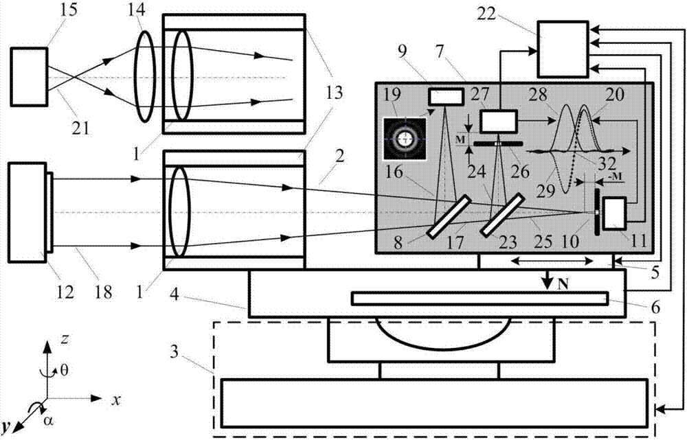
[0065] Such as figure 2 As shown, the infinite and finite conjugate differential detection focus-finding photoelectric image analyzer includes: an illumination source system 30, an infinite conjugate target optical system 12, a finite conjugate target optical system 15, a measuring objective lens 14, and a zero diopter Collimating mirror 1, collimating mirror support mechanism 13, five-degree-of-freedom x-y-z-α-θ adjustment table 3, image analyzer support mechanism 4, x-direction focusing moving guide rail 5, x-direction focusing moving guide rail displacement monitoring system 6 , focus-finding clear image collector 7, computer measurement and control system 22, and the first beam splitter 8 integrated on the focus-finding clear image collector 7, area array detection CCD 9, second beam splitter 23, first pinhole 10, The first photodetector 11 , the second pinhole 26 and the second photodetector 27 .

[0066]...

Embodiment 2

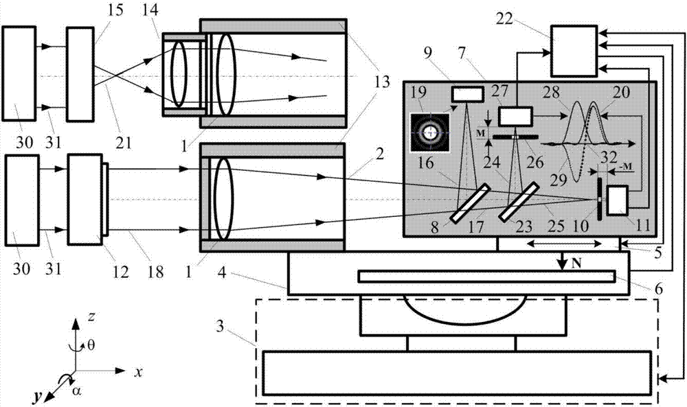
[0069] Infinity conjugate target optical system optical instrument measurement method reference image 3 The description is as follows: use the illumination source system 30 to irradiate the infinity conjugate target optical system 12 to form the target object, adjust the five degrees of freedom x-y-z-α-θ adjustment table 3 to make the infinity conjugate target beam 18 enter the zero-degree collimation mirror 1, and is converged into the image-side convergent beam 2, and the image-side convergent beam 2 is divided into two parts: the reflected image-side converged beam 16 and the transmitted image-side converged beam 17, by using the first beam splitter 8, and the computer measurement and control system 22 controls the x-direction The focus moving guide rail 5 enables the focus-finding clear image collector 7 to perform focus-finding scanning measurement on the converging point of the image-side converged beam 2 along the x direction, and the area array detection CCD 9 is used ...

Embodiment 3

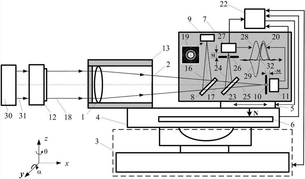
[0079] Reference for measurement methods of optical instruments for finite-distance conjugate target optical systems Figure 4 The description is as follows: assemble the measuring objective lens 14 on the collimator support mechanism 13, illuminate the finite-distance conjugate target optical system 15 with the illumination source system 30 to form the target object, and adjust the five degrees of freedom x-y-z-α-θ adjustment table 3 to make the finite The light beam 21 at the object side of the far conjugate target enters the measuring objective lens 14 and the zero-diopter collimating mirror 1, and converges the converging light beam 2 at the imaging side through the collimating mirror 1 at zero diopter, and divides the converging light beam at the image side into two parts by using the first beam splitter 8. For reflecting the converged light beam 16 on the image side and transmitting the converged light beam 17 on the image side, the computer measurement and control system...


PUM


Abstract

The invention belongs to the technical field of photoelectricity testing, and relates to an infinite and finite conjugated differential detection focusing photoelectric image analyzer which integrates light, machine, electricity, arithmetics and automatic control and a realizing method thereof. According to the invention, clear acquisition and focus fixing of a reflection light path target image are realized through high precision differential confocal focusing of a transmission light path; finite conjugated optical system parameters are tested by adding an optical-electric image analyzer measurement objective lens; through translation and rotation of the photoelectric image analyzer, optical parameters of optical system axis and out-of-axis fields and a folding axis system are measured; and finally high-precision comprehensive test of axis and out-of-axis field optical parameters of an infinite and finite conjugated target optical imaging system is realized. The infinite and finite conjugated differential detection focusing photoelectric image analyzer can precisely, rapidly and automatically collect, analyze and process images of the optical system through a corresponding measurement method and software control, so as to acquire performance parameters of an infinite and finite conjugate photoelectricity instrument.

Description

technical field [0001] The invention relates to an infinite and finite conjugate differential detection focus-finding photoelectric image analyzer, which belongs to the technical field of photoelectric testing. [0002] technical background [0003] Photoelectric image analyzer is the basic unit of photoelectric test equipment, and its performance directly determines the degree of integration and high reliability of photoelectric test equipment. The photoelectric image analyzer is a comprehensive photoelectric test device integrating light, mechanics, electricity, calculation and automatic control. It is used to collect and process the target image formed by the optical system under test, in order to obtain various Module components of various performance parameters. [0004] In the complex photoelectric imaging system, there are many infinite conjugate optical imaging systems and finite conjugate optical imaging systems, and the key to realize the comprehensive measurement ...

Claims


Application Information

Patent Timeline
Patent Type & Authority Patents(China)
IPC IPC(8): G01M11/02
CPCG01M11/00
Inventor 赵维谦邱丽荣
Owner BEIJING INSTITUTE OF TECHNOLOGYGY
Why Eureka
Try Eureka