Polarized infrared spectrometer

An infrared spectrometer and infrared light source technology, applied in the field of polarization infrared spectrometer, can solve the problem of not being able to collect spectra at the same time

Active Publication Date: 2016-11-09
BEIJING UNIV OF CHEM TECH
View PDF15 Cites 4 Cited by
  • Summary
  • Abstract
  • Description
  • Claims
  • Application Information

AI Technical Summary

Problems solved by technology

But so far, the Fourier transform infrared spectroscopy instruments developed by all manufacturers have only one detector, which cannot simultaneously collect parallel bands A at the same time. // and vertical band A ⊥ spectrum
To observe the orientation behavior of molecular segments during stretching of polymer materials, and to continuously measure

Method used


Image

  • Polarized infrared spectrometer
  • Polarized infrared spectrometer
  • Polarized infrared spectrometer

Examples


Embodiment approach 1

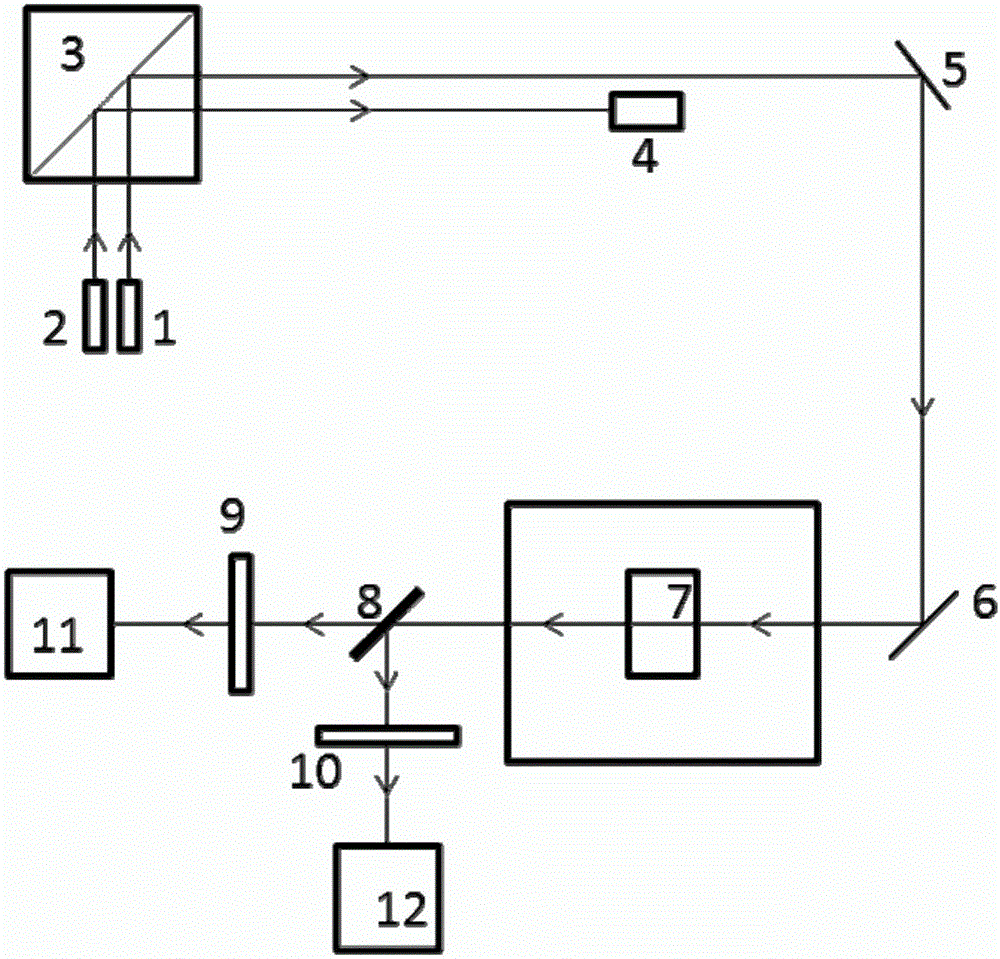
[0021] as attached figure 1 As shown, a polarized infrared spectrometer is characterized in that: at least by 1 infrared light source 1, 1 laser 2, 1 interferometer 3, 1 laser detector 4, 2 mirrors, 1 transmission accessory 7, A beam splitter 8, 2 polarizers, and 2 detectors are composed; a light source 1 and a laser 2 are placed under the interferometer 3, and a laser detector 4 and a first mirror 5 are placed on the right side of the interferometer. Place the second reflector 6 under the reflector 5; in front of the second reflector 6 are the transmission sample attachment 7 and the beam splitter 8; place the first polarizer 9 and the first detector 11 in front of the 8, respectively Place the second polarizer 10 and the second detector 12 to form a dual optical path system;

[0022] The light emitted by the light source 1 and the laser 2 enters the interferometer 3, and the light of the laser passing through the interferometer is detected by the laser detector 4; the infra...

Embodiment approach 2

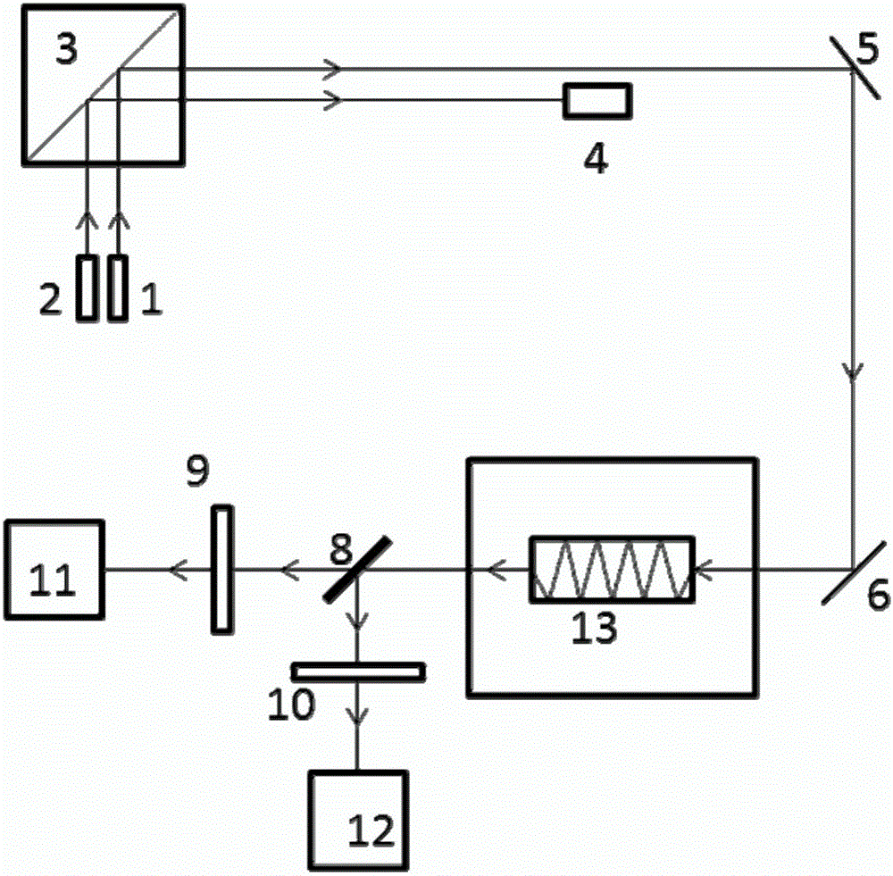
[0024] Embodiment 2 differs from Embodiment 1 in that the transmission measurement accessory 7 is changed to the ATR measurement accessory 13, and the structure is the same as figure 1 same. The spectrometer consists of 1 infrared light source 1, 1 laser 2, 1 interferometer 3, 1 laser detector 4, 2 infrared mirrors, 1 ATR accessory 7, 1 beam splitter 8, and 2 polarizers 9 , 10, two infrared detectors 11,12, and a spectrum sampling circuit system matched with the two detectors. A light source 1 and a laser 2 are placed under the interferometer 3, a laser detector 4 and a reflector 5 are placed on the right side of the interferometer, and an infrared reflector 6 is placed under the 5. In front of 6 are ATR sampling accessories 13 and beam splitter 8 . The spectrometer can simultaneously obtain the parallel polarization spectrum and vertical polarization spectrum of the sample.

[0025] The light emitted by the light source 1 and the laser 2 enters the interferometer 3, and th...

Embodiment approach 3

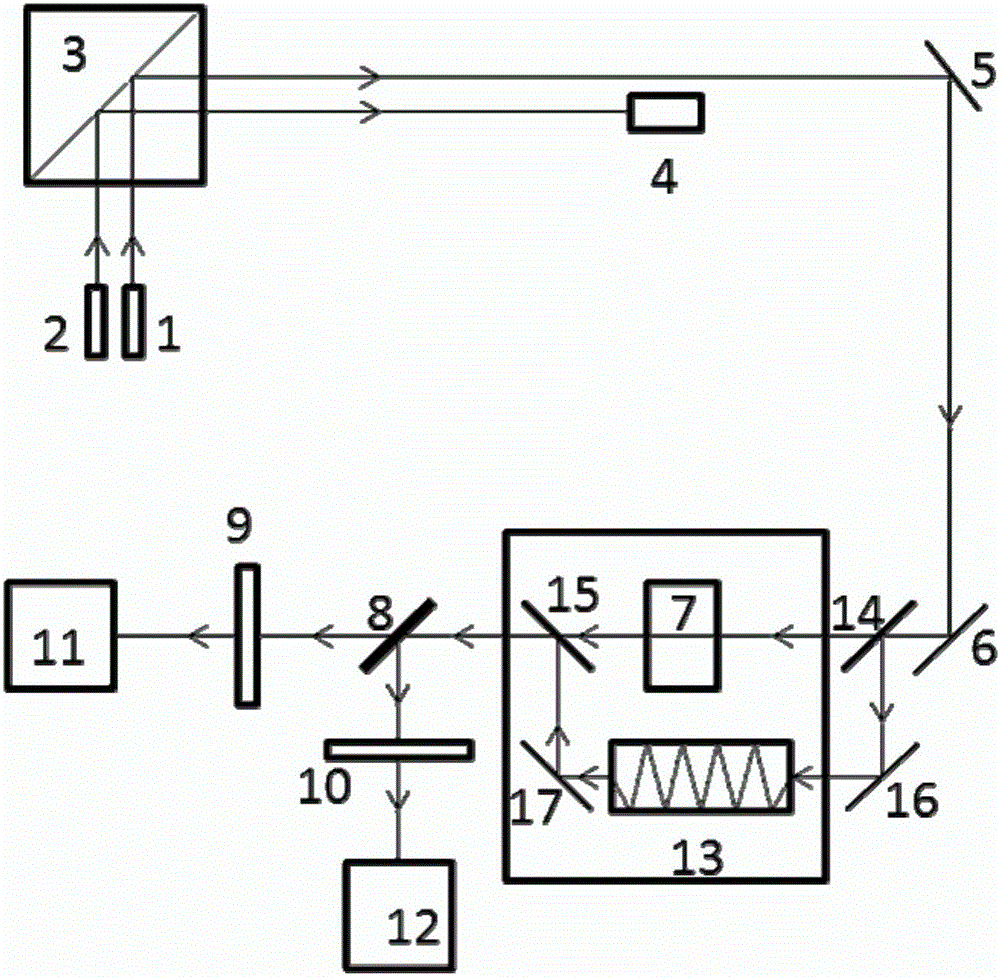
[0027] The difference between Embodiment 3 and Embodiments 1 and 2 is that this embodiment has a transmission attachment and an ATR attachment, and the structure is as follows image 3 shown. and figure 1The difference is that an ATR measurement accessory 13 is added below the transmission accessory 7, a chopper mirror is added before and after the transmission accessory, and an infrared reflector is added before and after the ATR accessory. The spectrometer consists of 1 infrared light source 1, 1 laser 2, 1 interferometer 3, 1 laser detector 4, 1 beam splitter 8, 2 polarizers 9, 10, 2 infrared detectors 11, 12 , one transmission attachment 7, one ATR attachment 13, two chopper mirrors 14, 15, four reflection mirrors 5, 6, 16, 17, and a spectrum sampling circuit system matched with two detectors.


PUM


Abstract

The invention provides a polarized infrared spectrometer which consists of, at least, one infrared light source, one interferometer, one beam splitter, one sample testing accessory, one laser device, one laser detector, two polarizing films, two infrared detectors and spectrum sampling circuit systems matched with the two detectors. The spectrometer is characterized in that the light passing through the sample testing accessory is split into two same light beams, then the two light beams respectively pass through the polarizing films on respective light paths and then are detected by the detectors on the respective light paths to obtain interferograms, the interferograms are finally subjected to Fourier transform processing, and meanwhile a parallel polarization spectrum and a vertical polarization spectrum of a sample are obtained.

Description

technical field [0001] The invention belongs to the technical field of spectrum analysis instruments, and relates to a polarized infrared spectrometer. Background technique [0002] The infrared dichroism method is a method for measuring the infrared spectrum of a sample based on infrared polarized light. Molecular infrared activity depends on vibrational modes causing dipole moment changes. The greater the dipole moment change, the greater the absorption coefficient. The infrared absorption coefficient is also related to the direction of dipole moment change (that is, the direction of vibration). If the vector direction of the vibration transition moment is parallel to the electric vector direction of the incident light, its absorption is the strongest, which is called the parallel band A / / ; Conversely, if the two are perpendicular, there will be no absorption, called vertical band A ⊥ Such as figure 1 shown). The ratio of the two is called the dichroic ratio (R), R...

Claims


Application Information

Patent Timeline
IPC IPC(8): G01N21/19G01N21/35
CPCG01N21/19G01N21/35
Inventor 闫寿科宋春风李效玉袁洪福胡爱琴
Owner BEIJING UNIV OF CHEM TECH
Why Eureka
Try Eureka