Direction of Arrival Estimation System and Method for Smart Antenna Based on Empirical Mode Decomposition

An empirical mode decomposition and direction-of-arrival estimation technology, applied to radio wave measurement systems, instruments, etc., can solve problems such as limitations, poor real-time effects, and limited effects, and achieve the effect of improving suppression

Inactive Publication Date: 2018-07-24
HOHAI UNIV
View PDF4 Cites 0 Cited by
  • Summary
  • Abstract
  • Description
  • Claims
  • Application Information

AI Technical Summary

Problems solved by technology

Therefore, the Bartlett method with lower resolution is limited in practical applications
The MUSIC method has high resolution and good anti-interference effect, but the calculation complexity is high, the real-time effect is poor, and it is difficult to capture fast signal targets
At present, there are three main research ideas. The first is to find a new DOA estimation method with a small amount of calculation, but the resolution of such methods is often lower than that of the MUSIC algorithm; the second is to improve the existing DOA estimation method. , this type of method is actually a compromise between the amount of calculation and accuracy; the third type is to rationally design the hardware according to the operation process, this type of method is at the expense of hardware cost, and the effect is limited

Method used


Image

  • Direction of Arrival Estimation System and Method for Smart Antenna Based on Empirical Mode Decomposition
  • Direction of Arrival Estimation System and Method for Smart Antenna Based on Empirical Mode Decomposition
  • Direction of Arrival Estimation System and Method for Smart Antenna Based on Empirical Mode Decomposition

Examples


Embodiment Construction

[0070] The technical solution of the present invention will be further introduced below in combination with specific embodiments.

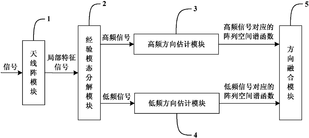
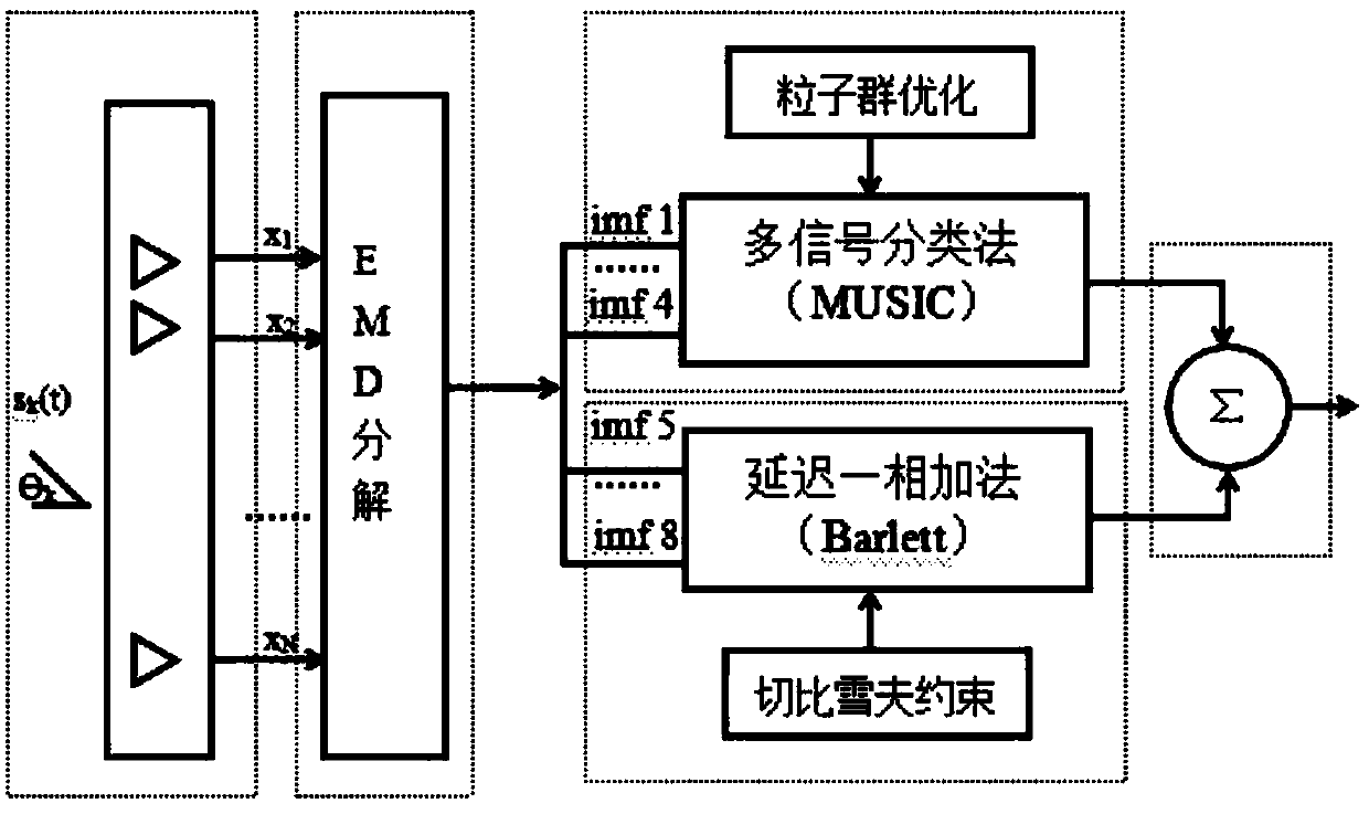
[0071] The invention discloses a smart antenna direction-of-arrival estimation system based on empirical mode decomposition, such as figure 1 with figure 2 As shown, it includes the antenna array module 1, the antenna array module 1 receives the signal and transmits it to the empirical mode decomposition module 2, the empirical mode decomposition module 2 decomposes the signal into local characteristic signals of different time scales, and the local characteristic signal The high-frequency signal is passed to the high-frequency direction estimation module 3 to obtain the array space spectrum function corresponding to the high-frequency signal, and the low-frequency signal in the local characteristic signal is passed to the low-frequency direction estimation module 4 to obtain the array space spectrum function corresponding to the low-frequency si...


PUM


Abstract

The invention discloses an intelligent antenna direction of arrival estimation system and an intelligent antenna direction of arrival estimation method based on empirical mode decomposition. The intelligent antenna direction of arrival estimation system comprises an antenna array module, which is used to receive a signal, and is used to transmit the signal to an empirical mode decomposition module. The empirical mode decomposition module is used to decompose the signal into local characteristic signals having different time scales. The high frequency signal of the local characteristic signals is transmitted to a high frequency direction estimation module, and an array space spectral function corresponding to the high frequency signal is acquired. The low frequency signal of the local characteristic signals is transmitted to a low frequency direction estimation module, and an array space spectral function corresponding to the low frequency signal is acquired. The array space spectral function corresponding to the high frequency signal and the array space spectral function corresponding to the low frequency signal are transmitted to a direction fusion module, which is used to accumulate the two array space spectral functions correspondingly. By searching the peak value of the accumulated array space spectral function, the direction of arrival of the signal is determined. By giving consideration to calculation complexity and resolution ratio, fast signal targets are acquired accurately in a complicated electromagnetic environment.

Description

technical field [0001] The invention relates to a smart antenna, in particular to a system and method for estimating the direction of arrival of a smart antenna based on empirical mode decomposition. Background technique [0002] In recent years, smart antennas have unique advantages in improving system communication quality, alleviating the contradiction between insufficient spectrum resources and the increasing development of wireless communication, reducing system cost and improving system management level. At present, smart antenna technology is not only used in sonar, radar, and military anti-jamming communications to complete spatial positioning and filtering, but also combined with modern digital signal processing technology to form antenna beams in the baseband for mobile communications with complex radio wave propagation environments. After research, it is found that the smart antenna can generate spatially directional beams, align the main lobe of the antenna with ...

Claims


Application Information

Patent Timeline
Patent Type & Authority Patents(China)
IPC IPC(8): G01S7/02
CPCG01S7/02
Inventor 李娜殷兴辉李海涛李萍刘杰
Owner HOHAI UNIV
Why Eureka
Try Eureka