Dot matrix code recognition method

An identification method and dot matrix code technology, applied in the field of identification codes, can solve the problems of low identification rate, large amount of stored information, and high hardware cost, and achieve the effect of fast background processing, simple identification method, and low memory requirements

Active Publication Date: 2016-11-09
SOUTH CHINA UNIV OF TECH +1
View PDF4 Cites 13 Cited by
  • Summary
  • Abstract
  • Description
  • Claims
  • Application Information

AI Technical Summary

Problems solved by technology

In the process of use, due to the large amount of stored information, the hardware requirements in the recognition process, such as the CPU memory requirements for background processing, are relatively large, which makes the hardware cost of recognition relatively high. At the same time, due to the large amount of st

Method used


Image

  • Dot matrix code recognition method
  • Dot matrix code recognition method
  • Dot matrix code recognition method

Examples


Embodiment Construction

[0035] The preferred embodiments of the present invention will be described below in conjunction with the accompanying drawings. It should be understood that the preferred embodiments described here are only used to illustrate and explain the present invention, and are not intended to limit the present invention.

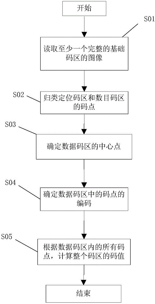
[0036] like figure 1 Shown, the recognition method of dot matrix code of the present invention, concrete steps are as follows:

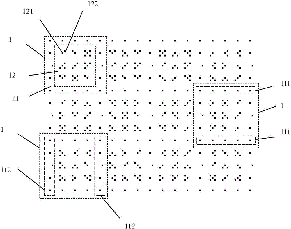
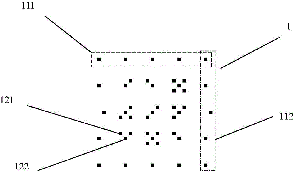
[0037] S01: Read at least one complete image of the basic code area 1, and the position of the code point is represented by a two-dimensional vector, namely (x, y); the dot matrix code is composed of several basic code areas 1, specifically as figure 2 and image 3 As shown, the basic code area 1 includes a positioning code area 11 and a data code area 12 .

[0038] S02: classify the code points in the basic code area 1 into the code points of the positioning code area 11 and the data code area 12, which are specifically as follows:

...


PUM


Abstract

The invention discloses a dot matrix code recognition method. The method is characterized by comprising the following steps: 1) an image of at least one complete basic code area is read, wherein the dot matrix code is formed by a plurality of basic code areas, and each basic code area comprises a positioning code area and a data code area distributed with code points respectively; 2) code points in the basic code area are classified into code points in the positioning code area and code points in the data code area; 3) the grid center formed by the code points in the positioning code area is defined as the central point of the data code area; 4) according to the number of code points in the data code area and the direction away from the central point of the data code area, codes of the code points in the data code area are determined; and 5) the codes of all code points in the data code area are combined to calculate the code value of the overall code area. By adopting the method of the invention, the recognition rate is high, the recognized hardware memory is lowly required, and the cost is low.

Description


Claims


Application Information

Patent Timeline
Owner SOUTH CHINA UNIV OF TECH
Why Eureka
Try Eureka