High voltage AC switchgear
A high-voltage AC and switchgear technology, applied in the busbar/line layout, substation/distribution device casing, etc., can solve the adverse effects of high-voltage AC switchgear reliability, difficult volume of high-voltage AC switchgear, and refusal of interlocking devices to move, etc. problems, to achieve the effect of reducing the number of switching elements, improving reliability, and reducing loop resistance
- Summary
- Abstract
- Description
- Claims
- Application Information
AI Technical Summary
Problems solved by technology
Method used
Image
Examples
Embodiment 1
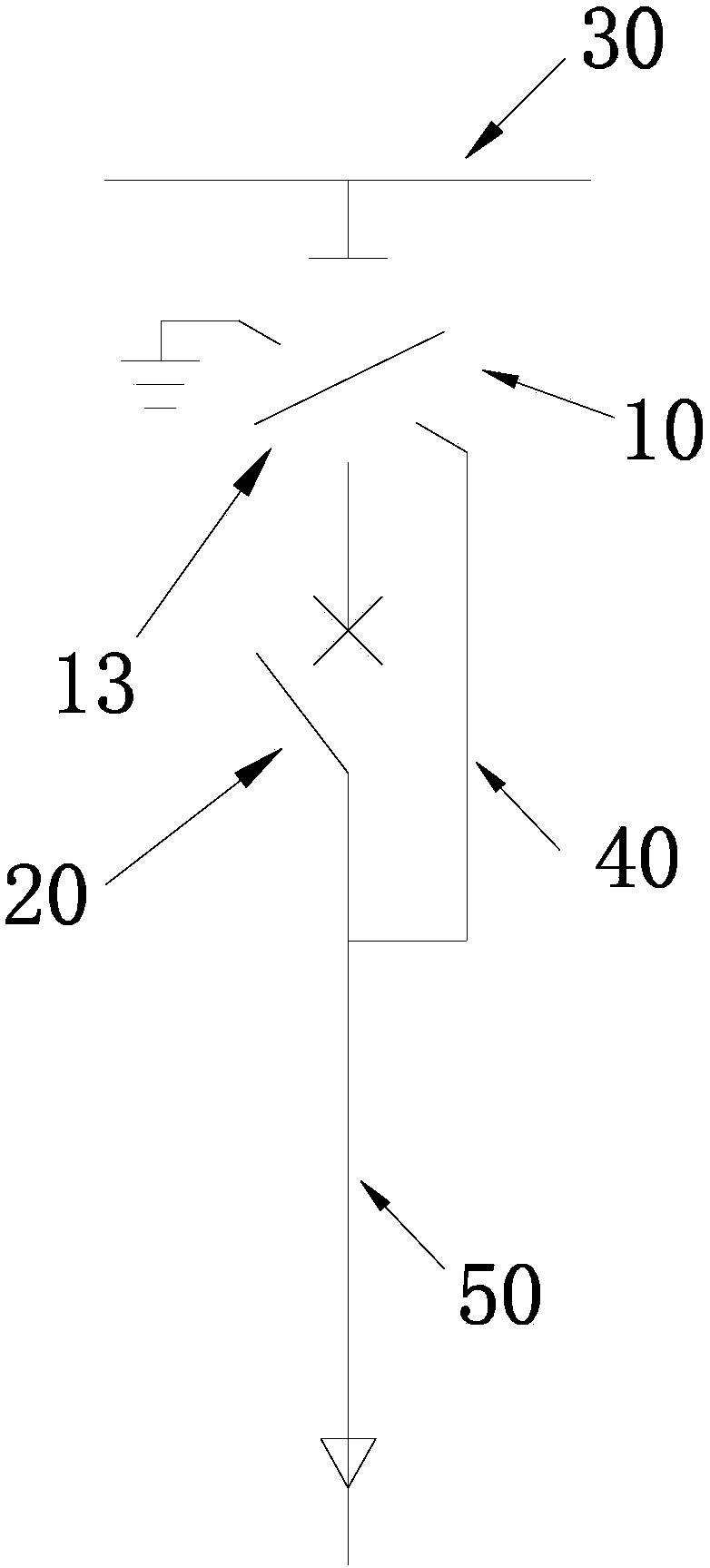
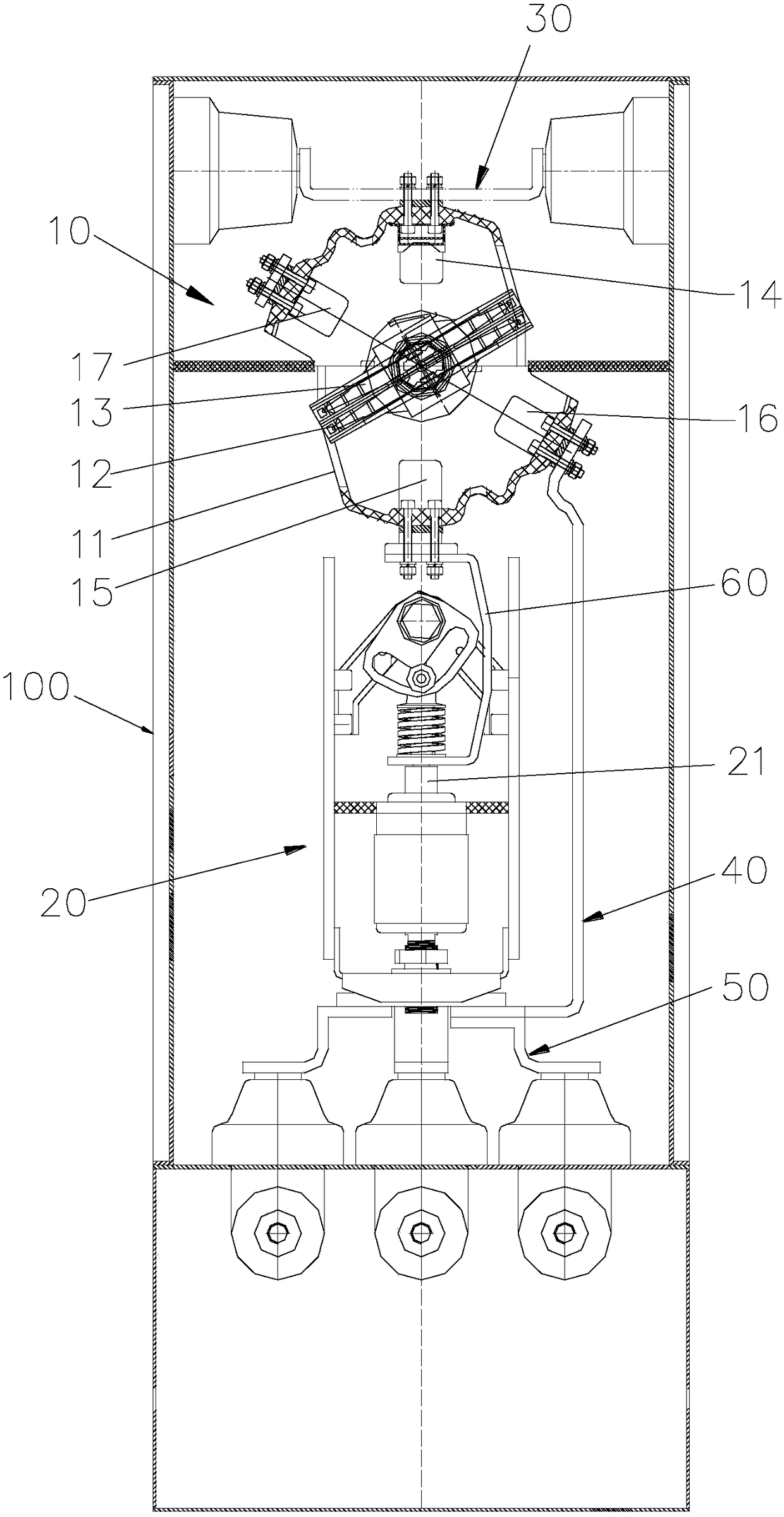
[0026] see figure 2 , a high-voltage AC switchgear proposed in Embodiment 1, the circuit part mainly includes a vacuum switch 20 and an integrated switch 10, and the integrated switch 10 is placed between the main bus 30, the vacuum switch 20 and the pre-grounded bus 40; the vacuum switch 20 and the branch The main bus 50 is electrically connected, and the branch main bus 50 is electrically connected to the pre-ground bus 40; the integrated switch 10 can connect the vacuum switch 20 to the main bus 30, or ground the pre-ground bus 40; the integrated switch 10 connects the vacuum switch 20 to the main When the bus 30 is connected, the integrated switch 10, the vacuum switch 20 and the branch main bus 50 constitute the main circuit; when the integrated switch 10 grounds the pre-grounded bus 40, the vacuum switch 20 is isolated from the main bus 30, and the integrated switch 10 and the pre-grounded bus 40 constitutes a ground loop. Therefore, in this embodiment, the pre-ground ...
Embodiment 2
[0032] see Figure 4 , the basic idea of the second implementation is consistent with that of the first example, the difference is only in the specific structural design of the integrated switch, that is, the integrated switch 10 of the first embodiment is a double-break design, while the integrated switch 10' of the second embodiment is a single-break design , specifically: the integrated switch 10 of Embodiment 1 has an upper main static contact 14, a lower main static contact 15, an insulating rotating shaft 13 and a three-phase moving contact 12, and the insulating rotating shaft 13 rotates to a non-working position state (that is, an isolation position state or ground position state), the two three-phase moving contacts 12 on the two ends of the insulating shaft 13 are separated from the main static contact 14 and the lower main static contact 15 by a certain distance, that is, double fractures are formed; and the implementation In the second example, there is no lower ...
PUM
 Abstract
Description
Claims
Application Information
 - R&D
- Intellectual Property
- Life Sciences
- Materials
- Tech Scout
- Unparalleled Data Quality
- Higher Quality Content
- 60% Fewer Hallucinations
Browse by: Latest US Patents, China's latest patents, Technical Efficacy Thesaurus, Application Domain, Technology Topic, Popular Technical Reports.
© 2025 PatSnap. All rights reserved.Legal|Privacy policy|Modern Slavery Act Transparency Statement|Sitemap|About US| Contact US: help@patsnap.com


