External rotor alternating current (AC) independent excitation permanent magnet reluctance motor

A reluctance motor and outer rotor technology, applied to synchronous motors with stationary armatures and rotating magnets, electric components, magnetic cores/yokes, etc., can solve problems affecting the magnetic stability of permanent magnet salient pole pairs

Inactive Publication Date: 2016-11-09
戴珊珊
View PDF4 Cites 7 Cited by
  • Summary
  • Abstract
  • Description
  • Claims
  • Application Information

AI Technical Summary

Problems solved by technology

The above-mentioned new motor still has the following deficiencies: 1. When the number of "excitation salient pole pairs" on the stator and the number of "permanent magnet salient pole pairs" on the rotor are relatively small
And then affect the magnetic stability of permanent magnet salient pole pairs

Method used


Image

  • External rotor alternating current (AC) independent excitation permanent magnet reluctance motor
  • External rotor alternating current (AC) independent excitation permanent magnet reluctance motor
  • External rotor alternating current (AC) independent excitation permanent magnet reluctance motor

Examples


Embodiment 1

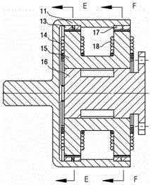
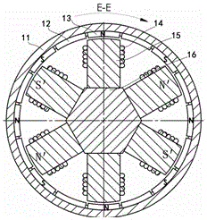
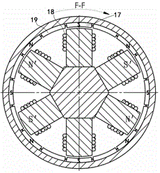
[0071] The structure of this embodiment is as attached Figure 1-5 shown.

[0072] Sixteen permanent magnets are arranged in pairs. Each group of permanent magnets is arranged on the inner wall of the rotating magnetic conduction cylinder 11 along the axial direction of the motor. Each group of permanent magnets forms a permanent magnet unit through the magnetic conduction cylinder 11 . as attached figure 1 middle. The permanent magnet 13 passes through the magnetic cylinder 11 . Together with the permanent magnet 17, a permanent magnet unit is formed. Eight sets of permanent magnet units are symmetrically arranged on the inner wall of the rotating magnetic cylinder. Sixteen magnetizers 12, 19 are in pairs. Each group of magnetizers is also arranged on the inner wall of the rotating magnetizer cylinder 11 along the axial direction of the motor. Each group of magnetizers forms a magnetizer unit through the magnetizer cylinder. The eight groups of magnetizer units are b...

Embodiment 2

[0080] The structure of this embodiment is as attached Figure 6-10 shown.

[0081] The structure of this embodiment is basically the same as that of the first embodiment. The difference is just that. The locations of the excitation coils wound around the periphery of the laminated iron core of the exciter unit are different.

[0082] The operating mechanism and torque formation of this embodiment are the same as those described in Embodiment 1. The description is not repeated here.

Embodiment 3

[0084] The structure of this embodiment is as attached Figure 11 And attached Figure 12 shown.

[0085] The rotor support in this embodiment is disc-shaped. Twelve permanent magnets and twelve magnetizers take the axis of the rotating shaft as the axis of symmetry. Inner rings and outer rings are alternately arranged on one side of the magnetic conduction disk 37 . The intervals between the inner ring permanent magnets 38 and the magnetizers are equal. The intervals between the outer ring permanent magnets 36 and the magnetizers 39 are also equal. Due to the magnetic conduction disc 37 conducts magnetism. The inner ring permanent magnet 38 and the outer ring permanent magnet 36 arranged on the same radial line form a permanent magnet unit. The N pole surface of the inner ring permanent magnet 38 is close to the magnetic conduction disk 37 , the S pole surface of the outer ring permanent magnet 36 is close to the magnetic conduction disk 37 , and the magnetic polarities...


PUM


Abstract

The invention relates to an external rotor AC independent excitation permanent magnet reluctance motor. The external rotor alternating current (AC) independent excitation permanent magnet reluctance motor is characterized in that a rotor support is provided with permanent magnet units and magnetizer units, which have the same quantity, and are arranged in an alternate, annular, and radially equalized manner, and in addition, gaps are arranged between the magnetizer units and the adjacent permanent units; during the rotation of the rotor support, all of the permanent magnet magnetic pole end surfaces of the permanent magnet units and all of the magnetizer end surfaces of the magnetizer units are capable of whisking excitation magnetic pole end surfaces of all of excitation body units on a stator base sequentially, and are superposed with the excitation magnetic pole end surfaces sequentially to form a shortest closed magnetic loop. The external rotor AC independent excitation permanent magnet reluctance motor is advantageous in that bad influences on the performance of the permanent magnet caused by current commutation of the excitation coils of the excitation body units are reduced, and the consumption of the permanent magnet is reduced, and excitation power supply commutation frequency is reduced, and the integral torque of the motor is improved; a parallelogram permanent magnet and magnetizer technical scheme provided by the invention is used to further eliminate a setback phenomenon, and then the operation of the motor is smoother.

Description

technical field [0001] The invention relates to an outer rotor permanent magnet reluctance motor. In particular, it is a permanent magnet reluctance motor with continuous torque and external rotor alternating current independent excitation. Background technique [0002] Traditional permanent magnet switched reluctance motors are undergoing continuous improvement in mechanical structure and control methods. recent years. In our country, a new type of "salient pole pair structure" motor with "excitation salient pole pair" and "permanent magnet salient pole pair" as the basic structural unit and a special excitation control method for this structure motor have appeared. See Chinese patents CN2011104562663, CN2011104562841, CN2013105845226, CN2013105844505. This new motor changes and shortens the "shortest closed magnetic circuit" of the traditional permanent magnet switched reluctance motor. The disclosed excitation control method of "excitation salient pole pair and perman...

Claims


Application Information

Patent Timeline
Patent Type & Authority Applications(China)
IPC IPC(8): H02K29/00H02K21/22H02K21/04H02K1/27H02K1/14
CPCH01F3/02H01F27/245H02K1/141H02K1/17H02K1/2786H02K1/28H02K21/046H02K21/22H02K29/00H02K2213/03H02K1/22
Inventor 戴珊珊朱石柱
Owner 戴珊珊
Why Eureka
Try Eureka