Engine control system

一种控制装置、发动机的技术,应用在发动机控制、自动控制、自动控制等方向,能够解决燃烧变动或偏差等问题

Active Publication Date: 2016-11-09
HITACHI ASTEMO LTD
View PDF25 Cites 4 Cited by
  • Summary
  • Abstract
  • Description
  • Claims
  • Application Information

AI Technical Summary

Problems solved by technology

In a gasoline engine equipped with an in-cylinder direct injection fuel supply device and an exhaust gas recirculation device, there are variations or deviations in the combustion implemented in the combustion chamber due to changes in the exhaust gas return flow rate of the exhaust gas recirculation device and the temperature of the exhaust gas return gas ( Hereinafter, referred to as the combustion variation) problem

Method used


Image

  • Engine control system
  • Engine control system
  • Engine control system

Examples


Embodiment 1

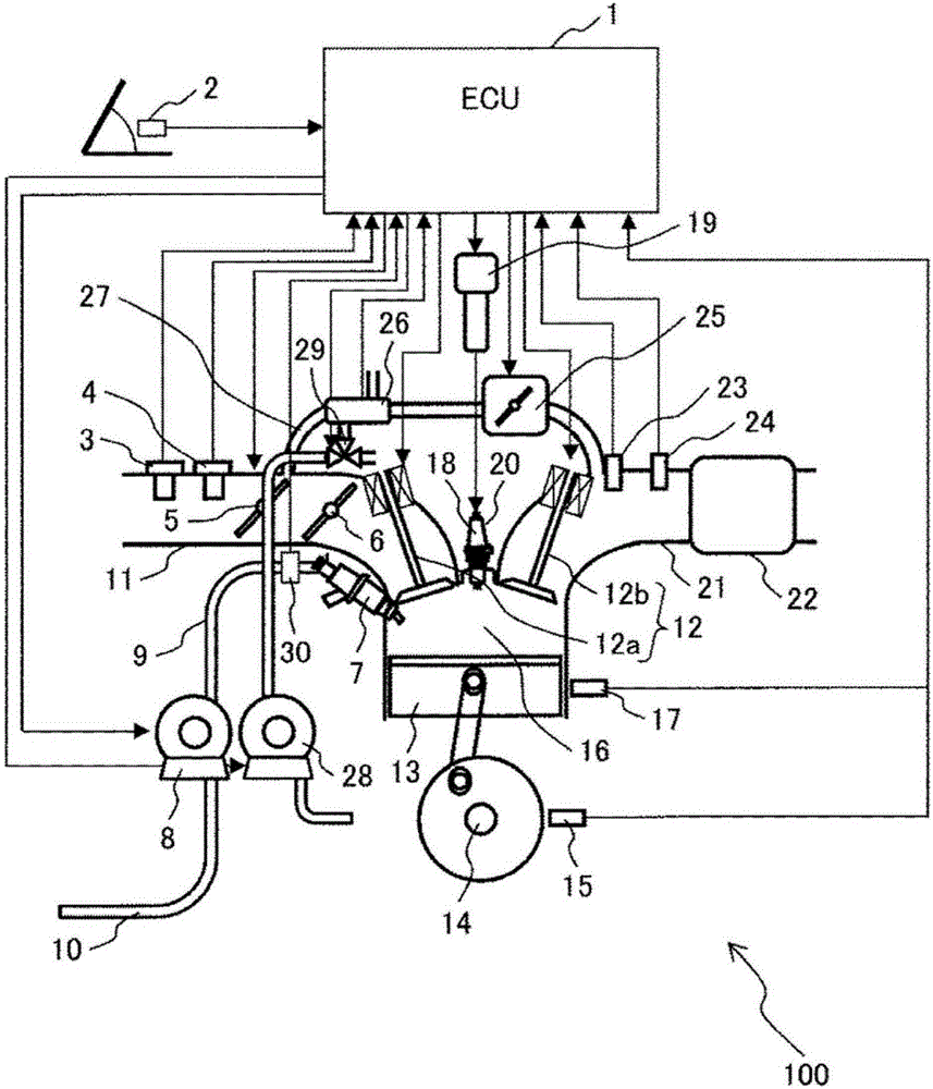
[0046] Next, use Figure 1 to Figure 13 , the configuration and operation of the engine control device according to the present embodiment will be described.

[0047] Figure 1 to Figure 13According to one embodiment of the present invention, it is a configuration diagram of a system in which an engine control device is applied to a gasoline engine for an automobile. device and a recirculation device for recirculating the exhaust gas toward the intake side, in the engine control device, the temperature of the exhaust gas recirculated by the recirculation device is higher than that of the lower case, or the exhaust gas is recirculated by the recirculation device When the amount of exhaust gas is larger than when the amount of exhaust gas is smaller, perform at least one of the following operations, that is, advance the fuel injection timing of the injection device, increase the fuel pressure supplied to the injection device, The number of split multi-stage injections performe...

Embodiment 2

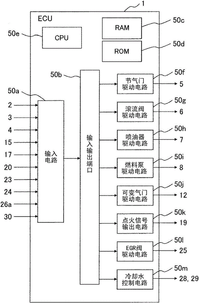
[0093] Next, use Figure 14 , Figure 15, Figure 16, Figure 17, Figure 18, Figure 19 , the second embodiment of the present invention will be described. In this example, use figure 1 The system described in is used as an automotive engine system. Additionally, use figure 2 The configuration described in hereinafter is used as the ECU 1 .

[0094] Figure 14 Regarding the present embodiment, it is a characteristic map of EGR control based on the intake air amount QA and the engine speed NE. The vertical axis represents the intake air amount QA, and the horizontal axis represents the engine speed NE. The EGR control determines the ranges of internal EGR, external EGR, and without EGR (without EGR) based on the intake air amount QA and the engine speed NE. At this time, the internal EGR controls the EGR flow through the variable intake and exhaust valves 12 . External EGR controls EGR flow through EGR valve 25 .

[0095] Figure 15A It is a characteristic diagram showi...


PUM


Abstract

The purpose of the present invention is to provide an engine control system that is capable of promoting mixing of fuel and air during exhaust gas recirculation, thereby suppressing combustion fluctuation of a gasoline engine, such that efficiency and exhaust gas purification can be simultaneously achieved. The engine control system controls an engine and is equipped with an injection device for injecting fuel directly into a cylinder and a recirculation device for recirculating exhaust gas to the intake side. When the temperature of the recirculating exhaust gas recirculated by the recirculation device is high as opposed to when the temperature is low, or when the amount of the recirculating exhaust gas recirculated by the recirculation device is large as opposed to when the amount is small, at least one of the following is executed: advancing of the fuel injection timing (IT_SP (n-2) of the injection device; increasing of the fuel pressure (FP) to be supplied to the injection device; reducing the frequency (n) of divided multi-stage injection to be performed by the injection device during the period between intake top dead center and compression top dead center; and reducing of the interval of divided multi-stage injection (IT_RE (n-2)).

Description

technical field [0001] The present invention relates to a control device for an engine mounted on a vehicle, and more particularly to a control device suitable for controlling an internal combustion engine that generates power by burning fuel in a combustion chamber. Background technique [0002] Today's automobiles require high efficiency and exhaust gas purification from the standpoint of environmental protection and effective use of resources. As a means of improving efficiency, gasoline engines equipped with in-cylinder direct injection fuel supply devices and exhaust gas recirculation devices have been developed. The in-cylinder direct injection fuel supply system uses a fuel injection valve (hereinafter referred to as an injector) to directly inject fuel into the combustion chamber and cool the combustion chamber to obtain the effect of suppressing abnormal combustion. The exhaust gas recirculation device recirculates the exhaust gas exhausted from the gasoline engine...

Claims


Application Information

Patent Timeline
Patent Type & Authority Applications(China)
IPC IPC(8): F02D41/02F01L13/00F02B31/00F02D13/02F02D21/08F02D41/32F02D41/34F02D43/00F02M26/00F02P3/045F02P9/00F02P15/10
CPCF02B31/06F02D13/0219F02D13/0261F02D21/08F02D37/02F02D41/0047F02D41/005F02D41/30F02D41/345F02D41/3836F02D41/401F02D41/402F02D2041/0015F02D2041/1472F02D2200/0602F02D2200/0606F02M26/15F02M26/28F02P5/1516F02P15/08Y02T10/12Y02T10/40F01P3/20F01P5/10F02P5/145
Inventor 绪方健一郎冈本多加志有原仪信
Owner HITACHI ASTEMO LTD
Why Eureka
Try Eureka