This helps you quickly interpret patents by identifying the three key elements:
Problems solved by technology
Method used
Benefits of technology
Problems solved by technology
[0007] It is known that in such a refrigeration cycle device using a non-azeotropic refrigerant mixture as a working refrigerant, since excess refrigerant rich in high-boiling point refrigerant is stored as liquid refrigerant in an accumulator or the like, the composition of the circulating refrigerant is known. Ratio changes, there is a possibility of failure due to performance degradation and high voltage rise (see Patent Document 2)
Method used
Image
Click on the blue label to locate the original text in one second.
Reading with bidirectional positioning of images and text.
Examples
Embodiment approach 1
[0042] First, the configuration of the refrigeration cycle apparatus in Embodiment 1 will be described.
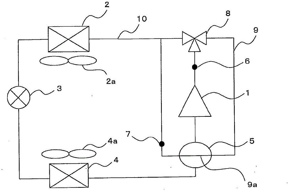
[0043] figure 1 It is a schematic configuration diagram of the refrigeration cycle apparatus in Embodiment 1.
[0044] like figure 1 As shown, the refrigeration cycle device in Embodiment 1 has a main path that sequentially connects the compressor 1, the condenser 2, the expansion valve 3, the evaporator 4, and the accumulator 5 (corresponding to the gas-liquid separator of the present invention). 10. In addition, the refrigerating cycle device has a bypass path 9 branched from the discharge side of the compressor 1 of the main path 10 , passes through the accumulator 5 via the three-way valve 8 , and communicates with the discharge side of the main path 10 . The inlet side of the condenser 2 is connected. And, these respective structural elements are connected by refrigerant piping.
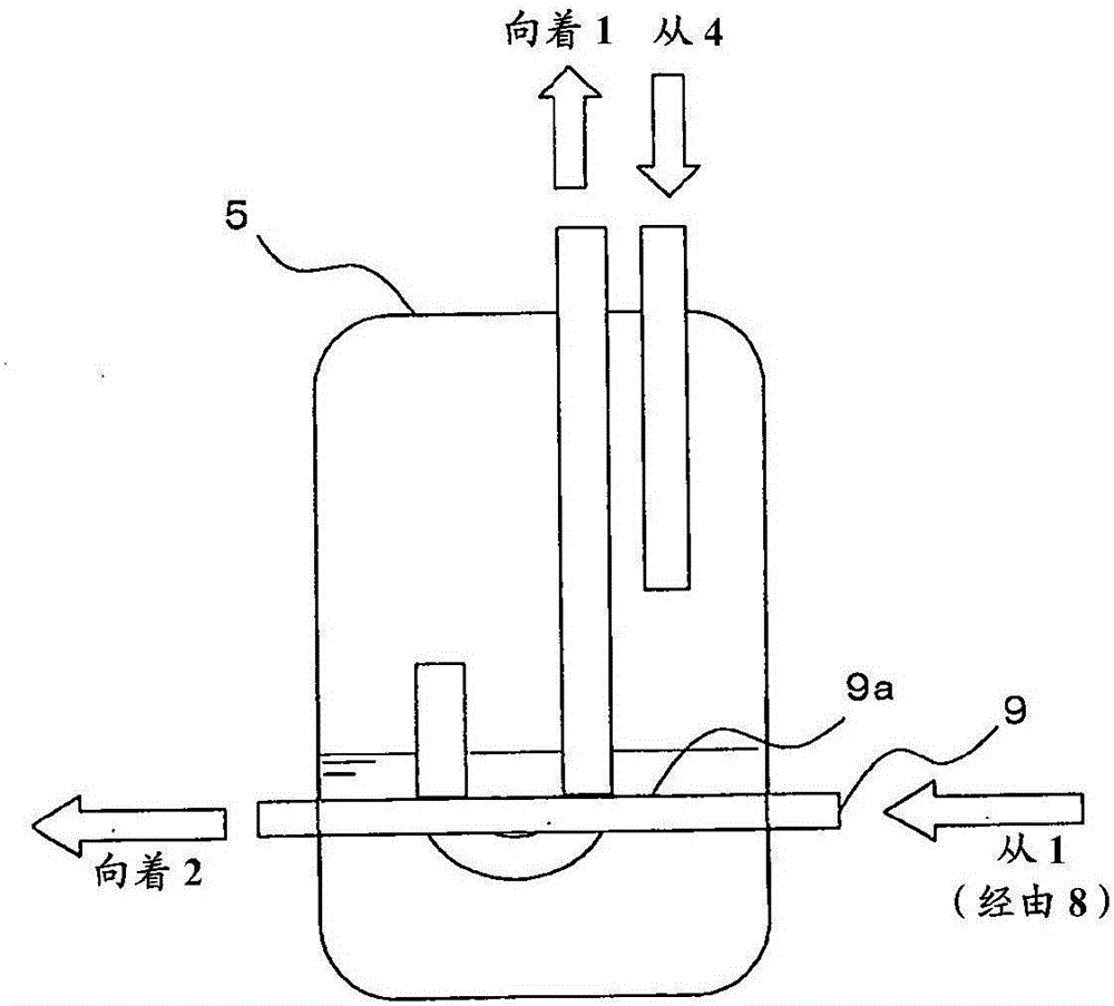
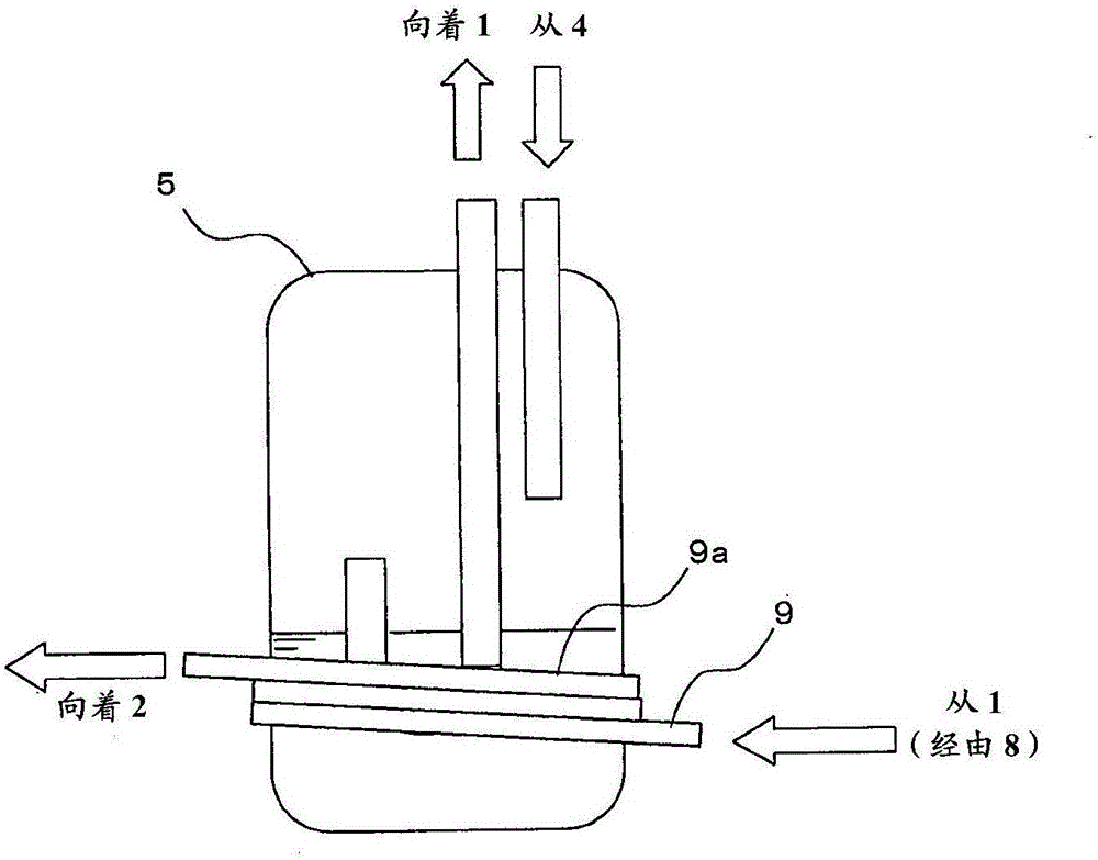
[0045] In addition, the bypass path 9 and the heat exchange portion 9a of the accum...
Embodiment approach 2
[0090] Next, the structure of the refrigeration cycle apparatus in Embodiment 2 is demonstrated.
[0091] Figure 10 It is a schematic configuration diagram of the refrigeration cycle apparatus in Embodiment 2.
[0092] In the refrigeration cycle apparatus of the second embodiment, the basic structure is the same as that of the first embodiment, but there is a difference in that a four-way valve 11 is provided on the downstream side of the three-way valve 8, and the flow direction of the refrigerant can be switched, Therefore, only this point will be described. In addition, the same reference numerals are assigned to the same constituent elements as in Embodiment 1 (in Embodiment 1, the heat exchanger is divided into a condenser 2 and an evaporator 4, and in Embodiment 2, by switching the four-way valve 11, the condenser 2 can sometimes function as an evaporator, and evaporator 4 can sometimes function as a condenser).
[0093] Next, the operation of the refrigeration cycle...
Embodiment approach 3
[0103] Next, the structure of the refrigeration cycle apparatus in Embodiment 3 is demonstrated.
[0104] Figure 13 It is a schematic configuration diagram of the refrigeration cycle apparatus in Embodiment 3.
[0105] In the refrigeration cycle apparatus in Embodiment 3, the basic configuration is the same as in Embodiment 1, but in the initial state of starting the operation, the discharge refrigerant of the compressor 1 is supplied to the accumulator 5, There is also a compressor heating mechanism 13 and an accumulator heating unit 14 in places where the refrigerant tends to accumulate when the compressor 1 and the accumulator 5 are stopped, and they are different in that they can be heated.
[0106] As the compressor heating mechanism 13 , for example, a heating mechanism that heats the compressor 1 by energizing (constrained energization) the motor coil without driving the motor inside the compressor 1 can be used, for example.
[0107] In addition, the outer surface o...
PUM
Abstract
The purpose of the present invention is to provide a safe and high-performance refrigeration cycle apparatus whereby, even when a refrigerant that can cause a disproportionation reaction is used as one component of a non-azeotropic refrigerant mixture in the refrigeration cycle apparatus, it becomes possible to avoid the refrigerant being exposed to a condition in which the disproportionation reaction can occur. A refrigeration cycle apparatus, in which a non-azeotropic refrigerant mixture is used as a working refrigerant, wherein the non-azeotropic refrigerant mixture comprises a first refrigerant and a second refrigerant having such a property that the boiling point of the second refrigerant can become higher than that of the first refrigerant under the same pressure. The refrigeration cycle apparatus is equipped with at least a main passage, wherein the main passage is composed of a compressor, a first heat exchanger, an expansion valve, a gas / liquid separator and a second heat exchanger which are connected in this order. In the refrigeration cycle apparatus, the first refrigerant has a property of causing a disproportionation reaction, and an initial operation for reducing the temperature or pressure of the refrigerant ejected from the compressor compared with that employed in an ordinary operation on the basis of the amount of the liquid refrigerant in the gas / liquid separator is carried out in an initial stage that is to be carried out subsequently to the starting up of the compressor.
Description
technical field [0001] The invention relates to a refrigeration cycle device using a non-azeotropic mixed refrigerant as a working refrigerant. Background technique [0002] In recent years, in order to suppress the influence on global warming, low-GWP refrigerants have been developed. R410A used in the past is a good refrigerant, but since its GWP (global warming coefficient) is about 2000, R32 with a GWP of about 1 / 3 of R410A is currently being used. R32 is a refrigerant with similar physical properties to R410A and good performance, with a GWP of about 600. In order to further reduce the GWP, fluoroethylene (HFO) refrigerants such as HFO-1234yf are being developed. [0003] However, this refrigerant is a refrigerant with a high boiling point and low performance. To maintain the same performance as in the past, there are many technical problems, and there is a possibility that the cost will increase. [0004] Accordingly, a refrigeration cycle device using a refrigerant...
Claims
Application Information
Patent Timeline
Application Date:The date an application was filed.
Publication Date:The date a patent or application was officially published.
First Publication Date:The earliest publication date of a patent with the same application number.
Issue Date:Publication date of the patent grant document.
PCT Entry Date:The Entry date of PCT National Phase.
Estimated Expiry Date:The statutory expiry date of a patent right according to the Patent Law, and it is the longest term of protection that the patent right can achieve without the termination of the patent right due to other reasons(Term extension factor has been taken into account ).
Invalid Date:Actual expiry date is based on effective date or publication date of legal transaction data of invalid patent.

