
High-precision tip pipe rolling machine

A tube coiling machine, high-precision technology, applied in application, fishing, fishing rods, etc., can solve the problems of rod body coiling, coiling distortion is not dense, rod body coiling distortion and looseness, etc., to achieve tight and seamless coiling Twisting, ensuring rolling effect, optimizing the effect of pressing strength

Active Publication Date: 2016-11-16
威海市通联精密机械有限公司
View PDF7 Cites 1 Cited by
  • Summary
  • Abstract
  • Description
  • Claims
  • Application Information

AI Technical Summary

Problems solved by technology

[0003] At present, in the rolling work of fishing rods, whether the coiling machine can roll the rod body firmly depends on whether the position of the pressure center of gravity of the upper workbench is accurate and reasonable. Traditional coiling machines are generally equipped with machine bases. There is a lower workbench above the machine base, which is connected to the machine base through the guide rails that move forward and backward. The movement of the lower workbench is controlled by the electrical control box in the machine base. The top of the table is equipped with an upper worktable for fixing and pressing the fishing rod to be rolled. The upper worktable is connected with the side of the machine base by a lifting cylinder that controls the upper worktable to move up and down. Due to the limitation of the main beam structure, the upper worktable can only move up and down through the lifting cylinder to fix the fishing rod rolled with the pressing belt. Especially when the length of the upper workbench is fixed, the position of the pressure center of gravity is fixed. When the length changes, it is impossible to ensure that the center of gravity is always kept in the middle of the fishing rod, resulting in a deviation in the pressure at the left and right ends of the fishing rod, and even the small end cannot be pressed at all, resulting in twisted and undense rolling, and because the tip of the fishing rod is thicker at one end It is thin, and the taper changes greatly. Its motion trajectory is arc-shaped during the rolling process. When the traditional coiler is working, the lower table only moves forward and backward. Due to the different diameters of the large and small ends of the fishing rod, during the rolling process , the line speed at both ends is inconsistent, causing the rod body to be twisted and loose. The guide rail that moves back and forth is connected with the lower worktable, and the movement of the lower worktable is controlled by the electrical control box in the machine base to move back and forth on the guide rail. The upper part of the lower worktable is used to fix and press the fishing rod to be rolled. The upper worktable is connected with the single cantilever main beam on the side of the machine base through the lifting drive cylinder that controls the upper worktable to move up and down. Because the lower worktable moves back and forth to roll, so for the cylindrical The rod can be fully sealed and rolled. At that time, there was a serious shortage of tapered fishing rods, especially for fishing rods with different tapers, the same cylindrical rod rolling method was used, and the final rolling There will be many defective products in the fishing rods that come out, which increases the workload and reduces work efficiency

Method used


Image

  • High-precision tip pipe rolling machine
  • High-precision tip pipe rolling machine

Examples


Embodiment Construction

[0019] Below in conjunction with accompanying drawing, the present invention is further described:

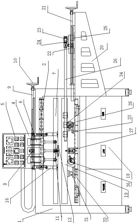
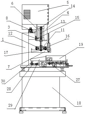
[0020]As shown in the accompanying drawings, a high-precision tip coiling machine is provided with a machine base 18 on which an upper working plate 7 and a lower working plate 19 are arranged. Composed of a rotary rolling mechanism with a lower working plate, the two sides of the machine base 18 in the pressing mechanism are respectively connected with the two side arms of the gantry-type main beam 1, and the front of the cross-arm of the gantry-type main beam 1 There are moving guide rails 2 on the side and upper side, the moving guide rail 2 on the front side of the cross arm of the gantry type main beam 1 is connected with the cylinder positioning box 4 through the guide block 3, and the upper end of the gantry type main beam 1 cross arm is provided with electrical control Box 5, the front end of the electrical control box 5 is connected to the upper end of the cylinder pos...


PUM


Abstract

The invention relates to the technical field of equipment machine manufacturing, in particular to a high-precision tip pipe rolling machine. The high-precision tip pipe rolling machine is provided with a machine body, and an upper working plate and a lower working plate are arranged on the machine body. The high-precision tip pipe rolling machine is characterized in that the machine body is composed of a pressing mechanism with the upper working plate, and a rotating rolling mechanism with the lower working plate; as the upper working plate capable of moving left and right is arranged in the pressing mechanism, the center of pressure gravity of a fishing rod to be rolled can be positioned through moving of the movable upper working plate, so that in the pressing process, it is ensured that the center of gravity is maintained in the middle of the fishing rod all the time, no deviation of pressure at the left large end and the right small end of the fishing rod exists, the small end can be pressed, and thus rolling is compact without warp; in the rotating rolling mechanism, as an arc rotating moving mode is adopted for the lower working plate and the center of gravity in rotation can move left and right, the rotating radius and the arc moving track are changed; the high-precision tip pipe rolling machine has the advantages that pressure is balanced, rolling is compact without warp, and the tensile strength of the tip of the fishing rod is high.

Description

technical field [0001] The invention relates to the technical field of equipment and machinery manufacturing, in particular to a high-precision tip coiled tube with balanced pressure, tight rolling without distortion, good straightness, low bending rate of the tip of the fishing rod, and high tensile strength of the tip of the fishing rod machine. Background technique [0002] At present, since the end of the 1980s, fishing rod manufacturing has been introduced from Japan to my country for more than 30 years. The fishing rod has changed from the original fiberglass rod to the current 40T high-carbon fishing rod. From materials to craftsmanship , Great changes have taken place. In order to meet the needs of fishing rod production, fishing rod equipment is becoming more and more sophisticated. Like other domestic industries, fishing rod special equipment has been independently developed from the initial imitation of Japanese and Korean equipment, and various new automatic, Semi...

Claims


Application Information

Patent Timeline
IPC IPC(8): A01K87/00
CPCA01K87/00
Inventor 于建超
Owner 威海市通联精密机械有限公司
Learn More