Steel tube perforating machine device and perforating method

A technology of punching machine and steel pipe, applied in the field of punching machine, can solve the problems of difficult to guarantee the shape and position tolerance, hidden danger, damage safety of the spreader, etc., and achieve the effect of improving the punching accuracy, ensuring the safety and ensuring the stability.

Active Publication Date: 2016-11-16
中冶辽宁德龙钢管有限公司
View PDF9 Cites 6 Cited by
  • Summary
  • Abstract
  • Description
  • Claims
  • Application Information

AI Technical Summary

Problems solved by technology

[0002] In recent years, large-diameter, large-wall-thick spiral welded pipes, straight seam welded pipes, and special-shaped steel pipes have been widely used in domestic and foreign port construction piling construction, large-scale structural parts main structure production, and steel structure workshop main beam and column construction. Traditional construction methods It is mainly for gas cutting hoisting holes or welding lugs at the symmetrical parts on both sides of the pipe end on site. It is difficult to guarantee the diameter of the gas cutting holes and the coaxiality tolerance; the process of welding the lifting lugs is cumbersome, and the shape and position tolerances are difficult to guarantee, which brings great inconvenience to the field use. It is very troublesome, and there is a safety hazard of damage to the spreader at the same time

Method used


Image

  • Steel tube perforating machine device and perforating method
  • Steel tube perforating machine device and perforating method
  • Steel tube perforating machine device and perforating method

Examples


Embodiment Construction

[0022] Embodiments of the present invention are further described below in conjunction with the accompanying drawings:

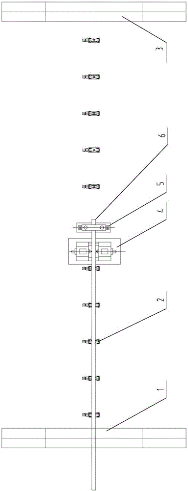
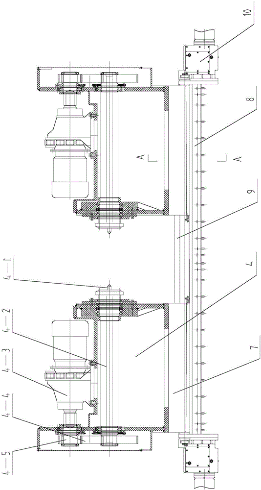
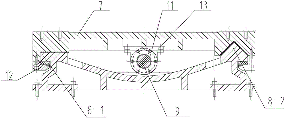
[0023] Such as Figure 1-Figure 4 As shown, a steel pipe punching machine device includes a pipe inlet stand 1, a conveying roller table 2, a bedside box, a steel pipe clamp 5, a pipe outlet stand 6, a pipe inlet stand 1, a conveying roller table 2, a bedside The box and the pipe outlet frame 3 are installed in sequence; the steel pipe fixture 5 is adjacent to the bedside box, and the bedside box includes two symmetrically arranged punchers 4 and a slide table 7 installed at the bottom of the puncher 4 , slideway 8, lead screw 9, screw nut 11, drive motor 10; two punchers 4 are respectively fixedly connected with two slide tables 7 by bolts, two slide tables 7 are slidingly connected with slideway 8, and lead screw 9 It is connected with the driving motor 10 in transmission, and the screw nut 11 is screwed on the lead screw 9, and the nut 11 is fixedly conn...


PUM


Abstract

The invention relates to a steel tube perforating machine device and a perforating method. A steel tube perforating machine comprises a tube feeding rack, conveying roller ways, a headstock, a steel tube clamp and a tube discharging rack. The steel tube clamp is adjacent to the headstock. The headstock comprises two symmetrically-arranged perforating machine bodies, sliding tables, a sliding way, a lead screw, a nut and drive motors, wherein the sliding tables, the sliding way, the lead screw, the nut and the drive motors are mounted at the bottoms of the perforating machine bodies. The two perforating machine bodies are fixedly connected with the two sliding tables through bolts correspondingly. The two sliding tables are in sliding connection with the sliding way. The lead screw is in transmission connection with the drive motors and is in screw joint with the nut. The nut is fixedly connected with the sliding tables through a nut seat. The section of one of the two sides, in sliding connection with the sliding tables, of the sliding way is square, and the section of the other of the two sides, in sliding connection with the sliding tables, of the sliding way is angular. According to the steel tube perforating machine device and the perforating method, based on the design of the sliding way of the perforating machine bodies, one side is square, the other side is angular, and therefore it is effectively guaranteed that radial movement does not happen during perforating, and perforating precision is improved; and the requirements of clients for safety, stability and accuracy in the use process are guaranteed.

Description

technical field [0001] The invention relates to a punching machine, in particular to a steel pipe punching machine device and a punching method for punching holes at the ends of steel pipes. Background technique [0002] In recent years, large-diameter, large-wall-thick spiral welded pipes, straight seam welded pipes, and special-shaped steel pipes have been widely used in domestic and foreign port construction piling construction, large-scale structural parts main structure production, and steel structure workshop main beam and column construction. Traditional construction methods It is mainly for gas cutting hoisting holes or welding lugs at the symmetrical parts on both sides of the pipe end on site. It is difficult to guarantee the diameter of the gas cutting holes and the coaxiality tolerance; the process of welding the lifting lugs is cumbersome, and the shape and position tolerances are difficult to guarantee, which brings great inconvenience to the field use. It is v...

Claims


Application Information

Patent Timeline
Patent Type & Authority Applications(China)
IPC IPC(8): B23B41/00B23B39/16B23Q3/08B23Q1/01
CPCB23B39/16B23B41/00B23B2215/72B23B2220/32B23Q1/017B23Q3/082
Inventor 李博王开寻薛俊
Owner 中冶辽宁德龙钢管有限公司
Why Eureka
Try Eureka