Gas protection device for front side of titanium alloy material weld joint

A gas shielding device, the technology of the front of the welding seam, which is applied to the device for supplying/removing shielding gas, welding equipment, welding accessories, etc., can solve the problems of poor reliability, short protection distance, unstable manual operation, etc., to reduce welding Effects of deformation, protection of the weld surface, flexibility and scalability benefits

Inactive Publication Date: 2016-11-16
BEIJING POWER MACHINERY INST
View PDF9 Cites 5 Cited by
  • Summary
  • Abstract
  • Description
  • Claims
  • Application Information

AI Technical Summary

Problems solved by technology

The vacuum argon-filled welding cabin is limited by the space of the equipment, which has restrictions on the size of the product, and the operability of welding in the cabin is poor, and the production efficiency is low; the special support method is better for automatic welding, and the manual welding The cover affects the operating angle of the welding torch and the sight line of the welding operator, and due to the instability of manual operation, the quality of manual welding of titanium alloys is unqualified and the reliability is poor
[0003] At present, the structure of the conventional titanium alloy manual argon arc welding cover is as follows: figure 1 As shown, there are the following defects in use: (1) To ensure the protective effect of the weld pool and the heat-affected zone, the welding torch must be kept perpendicular to the weld bead during welding operations, which affects the sight of the welding operator and is not conducive to observing the weld pool and heat-affected zone. Wire feeding operation can easily cause fluctuations in the welding process and lead to unstable quality; (2) This method has a short protection distance and is not suitable for continuous welding

Method used


Image

  • Gas protection device for front side of titanium alloy material weld joint
  • Gas protection device for front side of titanium alloy material weld joint
  • Gas protection device for front side of titanium alloy material weld joint

Examples


Embodiment Construction

[0023] The present invention will be described in detail below with reference to the accompanying drawings and embodiments.

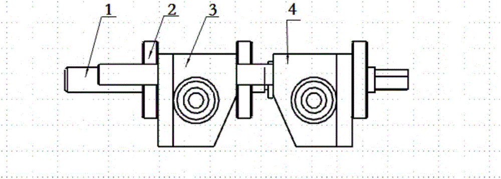
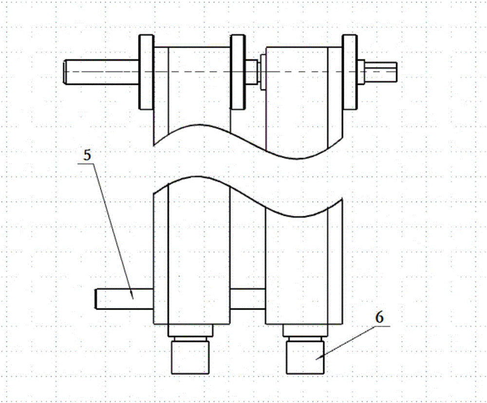
[0024] The invention provides a front gas protection device for a titanium alloy material welding seam, such as figure 2 and image 3 As shown, it includes connecting screw 1 and two ventilation sliders; the two ventilation sliders are respectively ventilation slider I3 and ventilation slider II4.

[0025] The two ventilation sliders are connected through a screw 1, and the distance between the two ventilation sliders is adjusted through a nut 2 matched with the screw 1, so as to achieve the best gas protection effect.

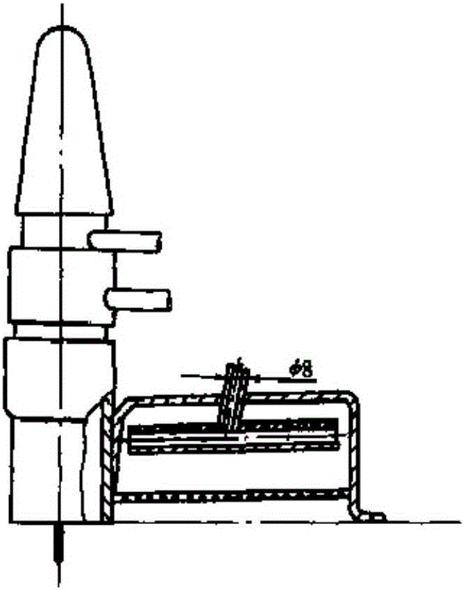
[0026] The ventilation slider is provided with an air inlet 6, and an air inlet channel 9 is processed along the air inlet 6 to the inside of the ventilation slider. The opposite surfaces of the two ventilation sliders are processed with more than one group of ventilation hole groups, and each group is connected to the ventilation blo...


PUM


Abstract

The invention discloses a gas protection device for the front side of a titanium alloy material weld joint. The gas protection device comprises a threaded rod and two ventilation sliding blocks. The two ventilation sliding blocks are connected through the threaded rod, and the distance between the two ventilation sliding blocks is adjusted through nuts matched with the threaded rod. Each ventilation sliding block is provided with an air inlet, and an air inlet channel is machined in the ventilation sliding block along the air inlet. One or more vent hole sets are machined in the opposite faces of the two ventilation sliding blocks. Each vent hole set comprises one or more vent holes. The vent holes communicate with the air inlet channels. The axes of the vent holes of each vent hole set are distributed in a radial mode on the section perpendicular to the axis of the corresponding air inlet channel with the projection point of the axis of the air inlet channel as the center. By the adoption of the gas protection device, the effect that the gas protection device is separated from a welding gun is achieved, welding operation is not affected by the gas protection device, and flexible operation as conventional welding can be achieved.

Description

technical field [0001] The invention belongs to the technical field of engine manufacturing, and in particular relates to a front gas protection device for a welding seam of a titanium alloy material. Background technique [0002] The chemical properties of titanium alloys are extremely active at high temperatures. Tests show that titanium quickly absorbs hydrogen at 300 °C, oxygen at 600 °C, and nitrogen at 700 °C, and the main components of air are oxygen and nitrogen, so reliable inert gas protection is the key to titanium alloy welding. At present, there are two forms of protecting titanium alloys with inert gas during the welding process: one is to weld in a vacuum argon-filled welding chamber, and the other is to fix a special support cover on the welding torch. The vacuum argon-filled welding chamber is limited by the equipment space, which has constraints on the size of the product, and the operability of welding in the chamber is poor, and the production efficiency...

Claims


Application Information

Patent Timeline
Patent Type & Authority Applications(China)
IPC IPC(8): B23K9/32B23K9/16
CPCB23K9/325B23K9/16
Inventor 刘志福杨月张亮王亚军马丽菊
Owner BEIJING POWER MACHINERY INST
Why Eureka
Try Eureka