Valve element steel ball assembling technology

An assembly process and steel ball technology, applied in metal processing, manufacturing tools, metal processing equipment, etc., can solve the problems of long adjustment time, high scrapping rate, and low processing efficiency, and achieve short adjustment time, low scrapping rate, and processing high efficiency effect

Active Publication Date: 2016-11-16
WUXI YINGBEI PRECISION BEARING
View PDF5 Cites 2 Cited by
  • Summary
  • Abstract
  • Description
  • Claims
  • Application Information

AI Technical Summary

Problems solved by technology

[0002] The spool is the main component of various hydraulic pumps and plunger pumps. The spool with different structures has different functions. The spool spool mainly moves laterally in the valve body through the spool to control the oil pressure at different positions. Control and feedback function, due to the high precision of the valve core and the valve body, in order to reduce wear, the valve core is required to have a certain oil storage capacity, that is, the valve core has an oil hole in the axial direction and is closed, and the steel ball seal is one of them. Finally, it is required that the steel ball will not loosen and slide out under a certain oil pressure. This type of valve core is a slender part, which is easy to bend and the steel ball is easy to loose during assembly. The adjustment time is long, the processing efficiency is low, and the scrap rate is high. , it is difficult to enter the stable mass production link

Method used


Image

  • Valve element steel ball assembling technology
  • Valve element steel ball assembling technology
  • Valve element steel ball assembling technology

Examples


Embodiment Construction

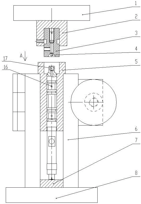
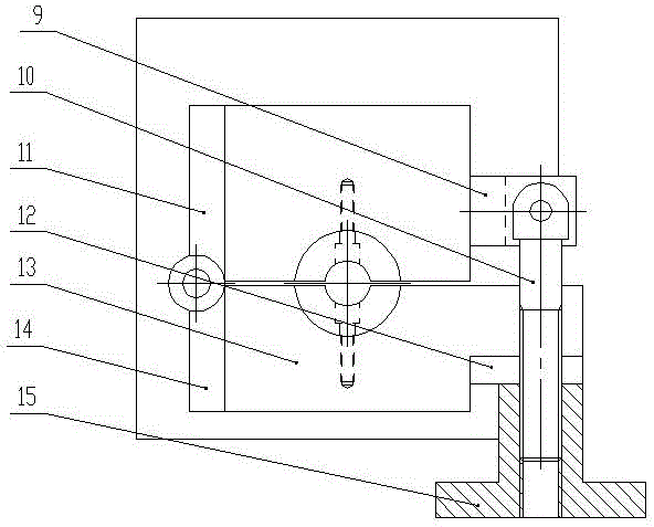
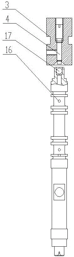
[0042] see Figure 1~Figure 6 , The invention relates to a valve core steel ball assembly and closing device, which includes a bottom plate 8, and a vertical plate 6 is arranged on the bottom plate 8, and the upper section of the vertical plate 6 is connected with a horizontally arranged rear side plate 9. The left end of the rear side plate 9 is provided with a first hinge 11, the front of the rear side plate 9 is provided with a front side plate 13, the left end of the front side plate 13 is provided with a second hinge 14, the first hinge 11 and the second hinge The hinge 14 is coaxially hinged up and down, the middle part of the rear side plate 9 is concave with a semicircular rear mold forward, the middle part of the front side plate 13 is concave with a semicircular front mold, the rear mold and Corresponding to the front mold, the rear mold and the front mold form the valve core back mold 5, the left end of the rear side plate 9 is provided with a screw 10 forward, and ...


PUM


Abstract

The invention relates to a valve element steel ball assembling technology. The valve element steel ball assembling technology is characterized by comprising the following steps that firstly, a valve element is fixed in a valve element profiling die; secondly, a steel ball is placed in the steel ball end of the valve element; thirdly, a power device is started, a pressing plate conducts downward pressing, a pressing head downwards presses the steel ball placed in the steel ball end of the valve element, meanwhile, a conical expanding section of an adjusting threaded sleeve descends accordingly, the closing-up operation is conducted on the steel ball end of the valve element, and the inner diameter of an upper opening of the closed-up steel ball end of the valve element is smaller than the diameter of the steel ball; and fourthly, after the steel ball of the valve element is subjected to assembling and closing-up operation, the power device drives the pressing plate to ascend, a locking screw sleeve is loosened, and the valve element is taken out. The valve element steel ball assembling technology has the beneficial effects that during assembling, bending is not likely to happen, and meanwhile the steel ball is not likely to loosen; and during assembling, the adjusting time is short, the machining efficiency is high, the rejection rate is low, and the stable volume production link can be achieved.

Description

technical field [0001] The invention relates to a valve core steel ball assembly process. Background technique [0002] The valve core is the main component of various hydraulic pumps and plunger pumps. Different structures of the valve core have different functions. The sliding valve core mainly moves laterally in the valve body through the valve core, and controls the oil pressure at different positions. For control and feedback, due to the high matching accuracy of the valve core and the valve body, in order to reduce wear, the valve core needs to have a certain oil storage capacity, that is, the valve core has oil holes in the axial direction and is closed, and the steel ball seal is one of them. Afterwards, it is required that the steel ball will not loosen and slip out under a certain oil pressure. This type of valve core is a slender part, which is easy to bend during assembly and the steel ball is easy to loosen. The adjustment time during assembly is long, the proce...

Claims


Application Information

Patent Timeline
Patent Type & Authority Applications(China)
IPC IPC(8): B23P19/00
CPCB23P19/00
Inventor 王杰张富严伟
Owner WUXI YINGBEI PRECISION BEARING
Why Eureka
Try Eureka