Interlayer connecting joint

An interlayer connection and node technology, which is applied to building components, walls, floors, etc., can solve the problems of difficult to guarantee grouting quality, easy destruction of concrete, unfavorable steel connection, etc., and achieve the effect of convenient construction, convenient construction and convenient hoisting.

Inactive Publication Date: 2016-11-16
初明进
View PDF6 Cites 2 Cited by
  • Summary
  • Abstract
  • Description
  • Claims
  • Application Information

AI Technical Summary

Problems solved by technology

Existing prefabricated concrete structure joints, especially the joints between the upper and lower walls of the wall structure, are generally weak links in the structure, which affect the mechanical performance; the connections between existing prefabricated components are generally reserved steel bars in the lower components, inserted into the In the upper part, such as steel sleeve grouting connection, grout anchor connection and other technologies to anchor the lower wall steel bars in the upper wall, the grouting needs pressure, the grouting quality is not easy to guarantee, and the construction is more complicated
[0003] In precast concrete structures, the horizontal joints between prefabricated components are generally on the top of each structural floor. For example, in a shear wall structure, the vertical distribution bars of the upper and lower walls are generally connected above the floor. Studies have shown that when the wall When cracking, it is unfavorable to the connection of components; especially the parts above the floors of the lower floors of the building are under greater stress, and the concrete is easy to be damaged under the load, which is not conducive to the connection of steel bars

Method used


Image

  • Interlayer connecting joint
  • Interlayer connecting joint
  • Interlayer connecting joint

Examples


Embodiment Construction

[0046] The interlayer connection node of the present invention will be described in detail below with reference to the drawings and embodiments.

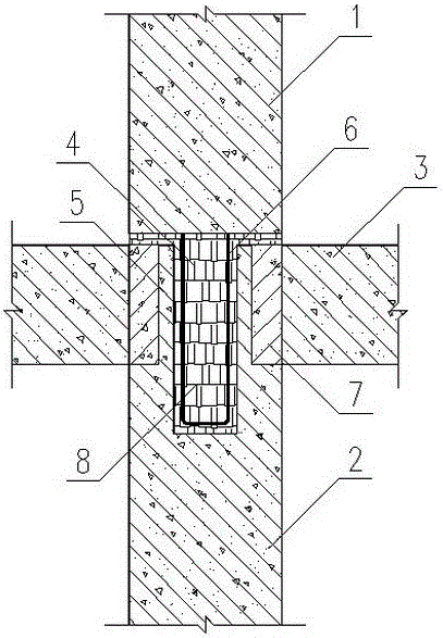
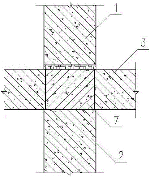
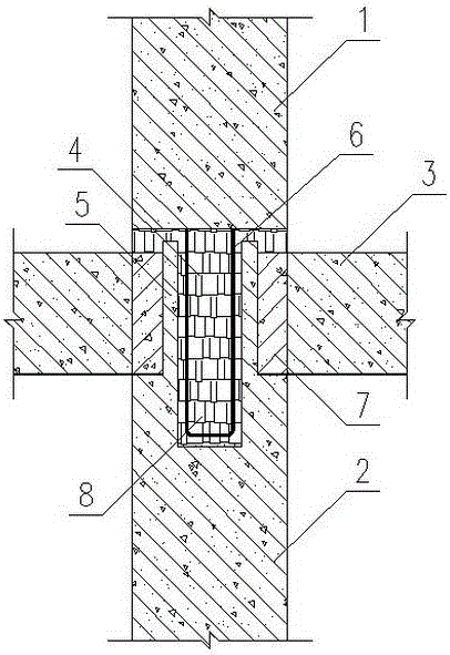
[0047] An embodiment of the interlayer connection node proposed by the present invention, such as figure 1 , figure 1 It is a schematic cross-sectional diagram of an interlayer connection node, and the cutting position is at the longitudinal hole position of the lower wall (the reinforcing bars not involved in the present invention are not drawn in the figure). The inter-layer connecting nodes include upper shear wall 1, lower shear wall 2 and prefabricated slab 3; the floor slab is prefabricated slab. The bottom of the upper wall 1 is pre-embedded with connecting steel bars 6, and the exposed part is U-shaped; the top of the lower wall 2 has a protrusion 5, and a longitudinal hole 4 is opened on the protrusion 5, and the protrusion 5 protrudes from the top surface of the lower wall 2 and the floor. The top surface is at the same ...


PUM


Abstract

The invention provides an interlayer connecting joint for shear walls and belongs to the technical field of building structures. An upper wall body and a lower wall body are connected into a whole by the aid of the joint; connecting reinforcing steel bars are embedded at the bottom of the upper wall body; a floor is arranged between the upper wall body and the lower wall body and is made of a precast slab or a laminated slab; the laminated slab comprises the precast slab and a post-cast layer; longitudinal holes are formed in the lower wall body; bulges which extend out of the top of the lower wall body and are located at the same elevation of the top surface of the floor or are higher than the elevation of the top surface of the floor are arranged in the longitudinal holes; the precast slab is placed at the top of the lower wall body; concrete is poured into space formed by the lower wall body and the precast slab; no concrete exists in the longitudinal holes; and after the concrete reaches preset strength, the upper wall body is mounted, the connecting reinforcing steel bars of the upper wall body are inserted in the longitudinal holes, a grouting material or the concrete is poured between the upper wall body and the floor and inside the preserved holes, and the upper wall body and the lower wall body are connected into the whole. With the joint, the integrity of the assembled integral concrete structure can be improved.

Description

technical field [0001] The invention belongs to the technical field of building structures, and in particular relates to an interlayer connecting node used for prefabricating and assembling an integral concrete structure. Background technique [0002] Prefabricated concrete structure is suitable for industrialization and is the development direction of housing industrialization. The connection structure between prefabricated components in precast concrete structures determines the overall performance of the structure. Existing prefabricated concrete structure joints, especially the joints between the upper and lower walls of the wall structure, are generally weak links in the structure, which affect the mechanical performance; the connections between existing prefabricated components are generally reserved steel bars in the lower components, inserted into the In the upper part, such as steel sleeve grouting connection, slurry anchor connection and other technologies to anch...

Claims


Application Information

Patent Timeline
Patent Type & Authority Applications(China)
IPC IPC(8): E04B1/38E04B2/00E04B5/02E04B5/17
CPCE04B1/38E04B2/00E04B5/02E04B5/17
Inventor 初明进
Owner 初明进
Why Eureka
Try Eureka