Rake dryer

A rake dryer and dryer technology, which is applied to local stirring dryers, dryers for static materials, dryers, etc., can solve the problems of increasing operating costs and reducing equipment use efficiency, so as to increase operating costs and reduce The effect of equipment usage efficiency

Inactive Publication Date: 2016-11-16
陈铭鸿
View PDF5 Cites 0 Cited by
  • Summary
  • Abstract
  • Description
  • Claims
  • Application Information

AI Technical Summary

Problems solved by technology

However, with the continuous progress of industrial technology, the requirements for equipment are getting higher and higher. Since the material is heated, evaporated and dried by the jacket outside the cylinder, and the stirring spindle and rake teeth in the center of the cylinder have no heating source, it is difficult for some thermally sensitive materials. High materials are easy to stick on the main shaft and rake teeth, which reduces the efficiency of equipment use and increases operating costs

Method used


Image

  • Rake dryer

Examples


Embodiment Construction

[0008] The specific implementation of the present invention will be further described below in conjunction with the examples. The following examples are only used to illustrate the technical solution of the present invention more clearly, but not to limit the protection scope of the present invention.

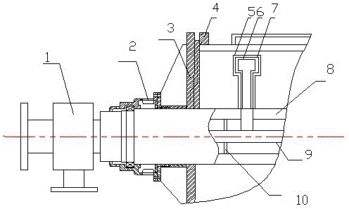
[0009] as attached figure 1 As shown, the rake-type dryer with rake teeth is provided with rake teeth and a hollow main shaft of the casing, and steam pipe branch pipes are arranged outside the rake teeth, and thermal insulation pipes are arranged outside the steam pipe branch pipes. There is a steam pipe in the main shaft, the steam pipe is fixed in the cavity through the cross positioning plate, the steam pipe is connected with the branch pipe of the steam pipe, and the end of the branch pipe of the steam pipe is opened; the shaft end of the casing hollow main shaft of the rake dryer is provided with a rotary joint, One end of the steam pipe is connected to the rotary joint...


PUM


Abstract

The invention discloses a rake dryer, which includes a rotary joint, a bearing seat, a dryer end cover, a flange, rake teeth, steam pipe branch pipes, a casing hollow main shaft, a steam pipe, a copper pipe, and a cross positioning plate. The casing hollow main shaft is equipped with a steam pipe, the rake tooth is equipped with a steam branch pipe, and the shaft end is provided with a rotary joint. The steam branch pipe is arranged outside the rake tooth, and the steam branch pipe is connected with the steam pipe. The purpose is to avoid some materials with high heat sensitivity from sticking on the main shaft and rake teeth.

Description

technical field [0001] The invention relates to a dryer, in particular to a rake dryer. Background technique [0002] The rake dryer is widely used in chemical industry, food, pharmaceutical, environmental protection and other industrial fields, especially suitable for drying paste materials that are not resistant to high temperature, flammable, and easily oxidized at high temperature. It has simple structure, convenient operation, and long service life. Long, stable and reliable performance, strong applicability. It uses the rotating main shaft to drive the rake teeth to evenly distribute the material in the cylinder on the cylinder wall, heat the material on the inner cylinder wall through the steam in the jacket, evaporate the water in the material, and vacuum the gas in the cylinder Discharge, so as to achieve the purpose of drying materials. However, with the continuous progress of industrial technology, the requirements for equipment are getting higher and higher. ...

Claims


Application Information

Patent Timeline
Patent Type & Authority Applications(China)
IPC IPC(8): F26B9/06F26B21/14F26B25/08
CPCF26B9/06F26B21/14F26B25/08
Inventor 陈铭鸿
Owner 陈铭鸿
Why Eureka
Try Eureka